The Open IPTV Forum has developed an end-to-end solution to allow any
consumer end-device, compliant to the Open IPTV Forum specifications,
to access enriched and personalized IPTV services either in a managed or
a non-managed network.
To that end, the Open IPTV Forum focuses on standardizing the
user-to-network interface (UNI) both for a managed and a non-managed
network, as depicted in Figure 1-1.
Figure 1-1: Open IPTV Forum scope
Throughout this document, the terms “Open Internet” and “Unmanaged
Network” are used interchangeably, to refer to the ability to access any
Service Provider using any Access Network Provider without any quality
of service guarantees.
This document also includes any errata identified in previous versions of this specification.
ETSI,
TS 102 084, "Digital Video Broadcasting (DVB); Remote Management and
Firmware Update System for DVB IPTV Services (Phase 2)"
[Ref-1]
Broadband Forum, TR-069, "CPE WAN Management Protocol"
[Ref-10]
IETF, RFC 3376, "Internet Group Management Protocol, Version 3", October 2002
[Ref-11]
IETF, RFC 4608, "Source-Specific Protocol Independent Multicast in 232/8", August 2006
[Ref-12]
ETSI, ES 282 003, "Resource and Admission Control Subsystem (RACS)"
[Ref-13]
ETSI, TS 102 539, "Carriage of Broadband Content Guide (BCG) information over Internet Protocol (IP)"
[Ref-14]
IETF, RFC 3550, "RTP: A Transport Protocol for Real-Time Applications"
[Ref-15]
3GPP,
TS 23.228, "3rd Generation Partnership Project; Technical Specification
Group Services and System Aspects; IP Multimedia Subsystem (IMS); Stage
2"
[Ref-16]
IETF, RFC 2617, "HTTP Authentication: Basic and Digest Access Authentication"
[Ref-17]
3GPP, TS 33.203, "3G security; Access security for IP-based services"
[Ref-18]
3GPP,
TS 24.229, "IP multimedia call control protocol based on Session
Initiation Protocol (SIP) and Session Description Protocol (SDP)"
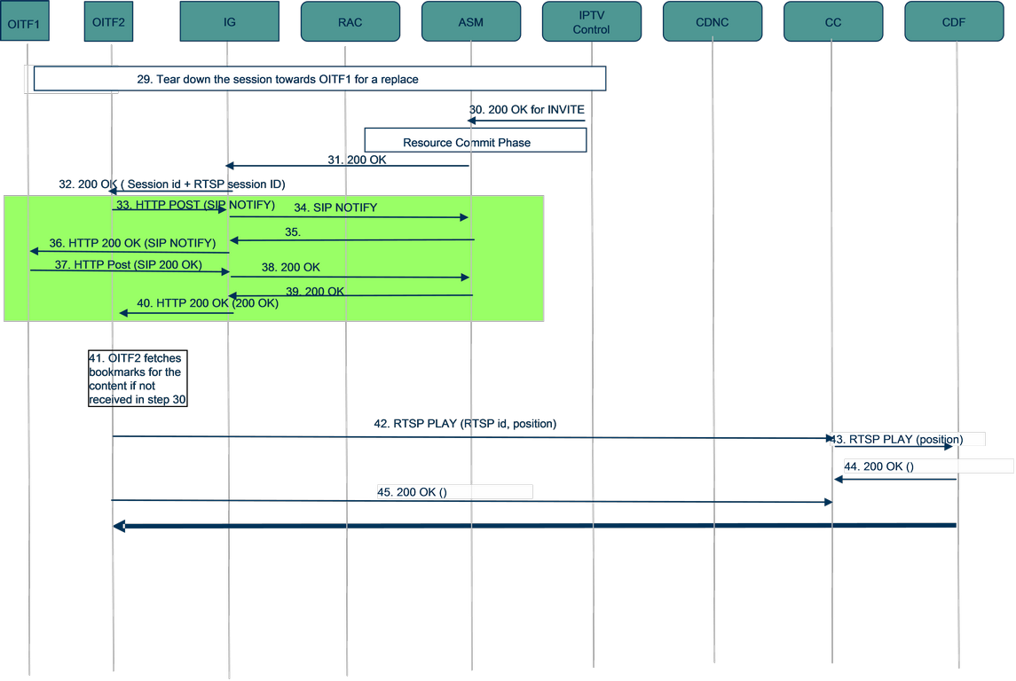
[Ref-19]
IETF, RFC 2326, "Real Time Streaming Protocol (RTSP)"
[Ref-2]
DLNA, Networked Device Interoperability Guidelines, October 2006 Note:
The above reference will be updated to the next release of the DLNA
Networked Device Interoperability Guidelines when these are published.
[Ref-20]
ITU-T, Recommendation E.164, "The international public telecommunication numbering plan"
IETF, RFC 6086, "Session Initiation Protocol (SIP) INFO method and Package Framework"
[Ref-48]
IETF, RFC 4301, "Security Architecture for the Internet Protocol"
[Ref-5]
IEEE, Std. 802.1Q-2003, "Ethernet Priority, Virtual Bridged Local Area Networks"
[Ref-50]
OASIS, "Profiles for the OASIS Security Assertion Markup Language (SAML) V2.0"
[Ref-51]
3GPP,
TS 26.237, "IP Multimedia Subsystem (IMS) based Packet Switch Streaming
(PSS) and Multimedia Broadcast/Multicast Service (MBMS) User Service;
Protocols (Release 8)"
[Ref-52]
3GPP2,
Technical Specification A.S0019-0, "Interoperability Specification
(IOS) for Broadcast Multicast Services (BCMCS)", Version 1.0, November
2004
[Ref-53]
3GPP2, Technical Specification X.S0022, "Broadcast and multicast service in cdma2000 wireless IP network"
[Ref-54]
"WiMAX
System Requirements, Network Protocols and Architecture for Multi-cast
Broad-cast Services (MCBCS Subteams Common Sections) - Part of Network
Release 1.5, Version 1.0.0"
[Ref-6]
IETF, RFC 2475, "An Architecture for Differentiated Services"
[Ref-7]
IEEE, 802.11, "Wireless Local Area Networks"
[Ref-8]
IETF,
RFC 4541, "Considerations for Internet Group Management Protocol (IGMP)
and Multicast Listener Discovery (MLD) Snooping Switches", May 2006
Open IPTV Forum, "Release 2 Specification, Volume 7 - Authentication, Content Protection and Service Protection", V2.3, January 2014.
[OIPF_DAE2]
Open IPTV Forum, "Release 2 Specification, Volume 5 - Declarative Application Environment", V2.3, January 2014.
[OIPF_PROT2]
Open IPTV Forum, "Release 2 Specification, Volume 4 - Protocols", V2.3, January 2014.
2.3 Informative references
No informative references.
3. Terminology and Conventions
3.1 Conventions
All sections and appendixes, except “Scope” and “Introduction”, are
normative, unless they are explicitly indicated to be informative.
3.2 Definitions
Term
Definition
Access Network
The network infrastructure used to deliver IPTV services to the Consumer.
The Access Network infrastructure (which may include the Internet) is
used for the delivery of the content and may include quality of service
management to ensure that appropriate network resources are available
for the delivery of the content.
Application
Collection of assets and logic that together
provide a Service to the User. Assets and logic may reside either in an
application Server or in the ITF or both.
Audience Research
A system to collect audience data,
under the explicit consent of the user. This system can be managed by
the IPTV Service Platform Provider, which collects audience data across
networks, platforms, different types of services and service providers.
Audience Research Data
Data on IPTV audience viewing
metrics i.e., the set of parameters and procedures that quantitatively
and qualitatively measure the consumed content (e.g. scheduled content,
CoD, PVR content), access and navigation (e.g. Content Guide,
subtitling), interactive applications (e.g. games, rating).
Consumer domain
The domain where the IPTV services are
consumed. A consumer domain can consist of a single terminal or a
network of terminals and related devices for service consumption.
Consumer Network
The local area network in which the
IPTV Terminal Function is located. Consumer Networks include residential
networks, hot spots, hotel networks etc.
Consumer(s)
See End User(s).
Content
An instance of audio, video, audio-video information, or data.
Content Guide
An on-screen guide to Scheduled Content
and Content on Demand, allowing a User to navigate, select, and discover
content by time, title, channel, genre, etc.
Content on Demand (CoD)
A Content on Demand service is a
service where a user can select the individual content items he or she
wants to watch out of the list of available content. Consumption of the
content is started on user request.
Content Protection
Means to protect content from unauthorized usage such as re-distribution, recording, playback, duplication etc
Content Provider
Entity that provides Content and associated usage rights to the IPTV Service Provider.
End User(s)
The individual(s) (e.g., members of the same family) who actually use the IPTV Services.
Internet
The Internet is the worldwide, publicly
accessible network of interconnected computer networks that transmit
data by packet switching using the standard Internet Protocol (IP).
ITF Remote Control Function
Function that allows the control of an ITF from a mobile or portable device.
IPTV Service Provider
Entity that offers IPTV Services and which has a contractual relationship with the Subscriber.
IPTV Solution
The specifications published by the Open IPTV Forum.
IPTV Terminal Function (ITF)
The functionality within the Consumer Network that is responsible for terminating the media and control for an IPTV Service.
IPTV User Profile
Information (e.g., viewing preferences) associated with a specific User who is a part of a subscription.
Local Storage
Content storage within the administrative
realm of the IPTV Service Provider, but not in their physical
environment (for example, local storage could be a partition of storage
located in the residential network and allocated to the IPTV Service
Provider to pre-load CoD).
Locally-controlled Local Personal Video Recorder (uLPVR)
Provision
of PVR functionality whereby the content is stored in the consumer
domain. No Service Provider intervention or permission is involved to
record content apart from content protection. This is referred to in
TISPAN as “Local PVR (lPVR).”
Service Provider-controlled Local Personal Video Recorder (sLPVR)
Provision
of PVR functionality whereby the content is stored in the consumer
domain but the content is recorded under Service Provider control. This
is referred to in TISPAN as “Client PVR (cPVR).”
Network Personal Video Recorder (nPVR)
Provision of PVR
functionality whereby the content is stored in the IPTV Service Provider
domain. The nPVR allows a user to schedule recording of scheduled
content programs. The user can later select the content they want to
watch from the recorded content.
Pay-per-View
The user is charged per selected and/or consumed content item. Can apply to both CoD and Scheduled Content Service.
Personalised Channel (PCh)
A particular list of programs
that is scheduled on the basis of the user’s preferences, viewing
habits or service provider recommendations, where each program is
selected from the Content Guide, e.g. BC services, CoD content. An
overlap or break may occur between the programs in a Personalised
Channel content guide.
Portal
A function of a Service Platform that provides an entry point to individual IPTV Services to Users via a GUI.
Program
A segment of Scheduled Content with a defined beginning and end.
Program Guide
See Content Guide.
Push CoD
A type of Content on Demand where the content
is pre-loaded to the ITF local storage by the IPTV Service Provider. The
user has no direct control of what content is downloaded; however the
IPTV Service Provider may make the choice based on user preferences and
habits. Content is available for direct consumption after the user
selection is confirmed.
Residential Network
Residential consumer network.
Scheduled Content
An IPTV service where the playout
schedule is fixed by an entity other than the User. The content is
delivered to the user for immediate consumption.
Service
Content and applications provided by Service Platform Providers and IPTV Service Providers.
Service Access Protection
Means to protect IPTV Services from unauthorized usage/access, such as - Access from unauthorized users - DOS attack
Service Platform Provider
Entity which, based on a
contractual relationship with IPTV Service Providers, provides the
supporting functions for the delivery of IPTV Services, such as
charging, access control and other functions which are not part of the
IPTV Service, but required for managing its delivery.
Service Protection
Means to protect contents (files or streams) during its delivery.
Session Portability
Ability of a given service/application to be switched from one device to another for a continuation of a session in real time.
Subscriber
The individual that makes the contract (subscription) with a Service Provider for the consumption of certain services.
Subscription Profile
Information associated with a subscription.
Trick Mode
Facility to allow the User to control the
playback of Content, such as pause, fast and slow playback, reverse
playback, instant access, replay, forward and reverse skipping.
User(s)
See End User(s).
3.3 Abbreviations
Abbreviation
Definition
ADSL
Asymmetric Digital Subscriber Line
AG
Application Gateway
AKA
Authentication and Key Agreement
AP
Access Point and Authentication Proxy
API
Application Programming Interface
A-RACF
Access Resource Admission Control Function
AS
Application Server
ASM
Authentication and Session Management
AV
Authentication Vector
A/V
Audio and Video
BCG
Broadband Content Guide defined by DVB
BTF
Basic Transport Function
CAC
Connectivity Admission Control
CAS
Conditional Access System
CC
Cluster Controller
CD
Content Delivery
CDC
Connected Device Configuration
CDF
Content Delivery Function
CDN
Content Delivery Network
CDNC
CDN Controller
CE
Consumer Equipment
CG
Content Guide
CK
Ciphering Key
CoD
Content on Demand
CPE
Customer Premise Equipment
CPI
Content Provider Interface
CSP
Content and Service Protection
CSPG
Content and Service Protection Gateway
DAE
Declarative Application Environment
DLNA
Digital Living Network Alliance
DLNA DMS
DLNA Digital Media Server
DLNA DMP
DLNA Digital Media Player
DOS
Denial of Service
DRM
Digital Rights Management
DSCP
DIFFServ Code Point
DTCP-IP
Digital Transmission Content Protection over Internet Protocol
DTT
Digital Terrestrial Television
DVB-IP
Digital Video Broadcasting Internet Protocol
ECM
Entitlement Control Message
ECMA
European Computer Manufacturers Association, ECMA
International - European association for standardizing information and
communication systems
EIT
Event Information Table
EPG
Electronic Program Guide
FCC
Fast Channel Change
FE
Functional Entity
GBA
Generic Bootstrapping Architecture
GENA
General Event Notification Architecture
GPON
Gigabit Ethernet Passive Optical Network
GUI
Graphical User Interface
HD
High Definition
HDMI
High Definition Multimedia Interface
HLA
High Level Architecture
HSS
Home Subscriber Server
HTTP
Hypertext Transfer Protocol
IAI
Internet Access Interface
IG
IMS Gateway
IGMP
Internet Group Management Protocol
IMPI
IMS Private User Identity
IMPU
IMS Public User identity
IMS
IP Multimedia Subsystem
IP
Internet Protocol
IPTV
Internet Protocol Television
IRCF
ITF Remote Control Function
ISIM
IMS Subscriber Identity Module
ISP
Internet Service Provider
ITF
IPTV Terminal Function
M/C-U/C
Multicast to Unicast
LAN
Local Area Network
MAC
Message Authentication Code
MCDF
Multicast Content Delivery Function
MDTF
Multicast Data Terminating Function
MSRP
Message Session Relay Protocol
NAT
Network Address Translation
nPVR
Network Personal Video Recorder
OIPF
Open IPTV Forum
OMA
Open Mobile Alliance
OITF
Open IPTV Terminal Function
PAE
Procedural Application Environment
P2P
Peer-to-Peer
PC
Personal Computer
PCh
Personalized Channel
PIM
Protocol Independent Multicast
PLMN
Public Land Mobile Network
POTS
Telephone Service
PPV
Pay-Per-View
QoS
Quality of Service
RA
Remote Access
RAC
Resource and Admission Control
RAND
Random Challenge
RCEF
Resource Control Enforcement Function
RET
Retransmission (server)
RTP
Real Time Protocol
RTCP
Real Time Control Protocol
RTSP
Real Time Streaming Protocol
RMS
Remote Management System
RUI
Remote User Interface
SAA
Service Access Authentication
SAML
Security Assertion Markup Language
SCART
Syndicat des Constructeurs d'Appareils Radiorécepteurs et Téléviseurs
S-CSCF
Serving Call Session Control Function
SD
Standard Definition
SD&S
DVB Service Discovery and Selection
SDP
Session Description Protocol
SLA
Service Level Agreement
SIM
Subscriber Identity Module
SIP
Session Initiation Protocol
SMPP
Short Message Peer-to-Peer
SMS
Short Message Service
SP
Service Provider
SPI
Service Provider Interface
SPDF
Service-based Policy Decision Function
SPP
Service Platform Provider
SSO
Single Sign-on
STB
Set Top Box
TBD
To Be Determined
TCI
Transport and Control Interface
TCP/IP
Transmission Control Protocol/Internet Protocol
UE
User Entity
UI
User Interface
UICC
Universal Integrated Circuit Card
UNI
User Network Interface
URI
Uniform Resource Identifier
URL
Uniform Resource Locator
USIM
Universal Subscriber Identity Module
VoD
Video on Demand
xDSL
Any DSL
WLAN
Wireless LAN
WG
WAN Gateway
WAN
Wide Area Network
XML
eXtensible Markup Language
XHTML
eXtensible Hypertext Markup Language
4. Introduction
4.1 IPTV Domains
The Open IPTV Forum recognizes the fact that there are various
domains within the end-to-end IPTV value chain that have different
administrative control or ownership. Thus, the Open IPTV Forum
architecture supports the existence of multiple entities with different
regions of administrative control and ownership interests.
Ownership and administrative control are impacted by a variety of
factors including the prevailing regulatory regimes, competitive
commercial environments, and the commercial strategies of the entities
involved. Ownership and administrative control may be considered
arbitrary boundaries within certain deployments.
The following domain framework although typical, does not prevent all
or some of these domains from being under a single administrative
ownership and control.
The architecture recognizes the following domains:
Consumer Domain: the domain where the IPTV services are
consumed. A consumer domain can consist of a single terminal or a
network of terminals and related devices for service consumption. The
device may also be a mobile end device; in this case, the delivery
system of a network provider is a wireless network. This domain is
within the scope for the Open IPTV Forum specifications.
Network Provider Domain: the domain connecting customers
to platform and service providers. The delivery system is typically
composed of access networks and core or backbone networks, using a
variety of network technologies. The delivery network is transparent to
the IPTV content, although there may be timing and packet loss issues
relevant for IPTV content streamed on IP. This domain is within the
scope of the Open IPTV Forum specifications.
Platform Provider Domain: the domain providing common
services (e.g., user authentication, charging etc.) to IPTV Service
Providers. Different types of service can be provided to a subscriber
including IPTV services, personalized communication services, etc. This
domain is within the scope for the Open IPTV Forum specifications.
IPTV Service Provider Domain: the domain providing IPTV
services to the Consumer Domain. In the context of television services
on IP, the IPTV Service Provider acquires/licenses content from Content
Providers and packages this into a service. In this sense the IPTV
Service Provider is not transparent to the application and content
information flow. This domain is within the scope of the Open IPTV Forum
specification
Content Provider Domain: the domain that owns or is
licensed to sell content or content assets. Although the Service
Provider is the primary source for the Consumer Domain, a direct logical
information flow may be set up between Content Provider and consumer
device e.g. for rights management and protection. This domain is within
the scope of the Open IPTV Forum specifications, primarily for the
aspect of acquisition of content by the service provider. Specifications
related to the content development processes of the content provider
are NOT considered in scope at this time.
4.2 The IPTV Value Chain
The Open IPTV Forum was established with the intent to specify common
and open architectures for supplying a variety of internet multimedia
and IPTV services to retail based consumer equipment. The two main
services are: Scheduled Content services (the IP equivalent to
conventional broadcast TV) and content on-demand content services. Both
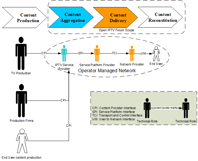
of those services follow the content value chain shown in Figure 4-1.
Figure 4-1: Content Value Chain
The content value chain is composed of the following roles to provide Scheduled Content and CoD services:
Content Production: producing and editing the actual content (movies, drama series, sports events, news reports etc.)
Content Aggregation: bundling content into catalogue offers and bouquets, ready for delivery
Content Delivery: transporting the aggregated contents to the consumer
Content Reconstitution: converting the content into a format suitable for rendering on the end-user device.
Each role in the value chain has historically been bound to a type of
stakeholder or technical role. Content Production, for example, is
linked to production firms and to the production teams of TV stations.
IPTV technology introduces a set of technical modifications to the
content chain that mainly encompasses content aggregation, delivery and
reconstitution. The Open IPTV Forum aims at specifying the technology
that delivers those three elements in the technical chain. The
aforementioned specifications can be distinguished in two main
categories:
The Managed Model: concerns access to and delivery of content services delivered over an end-to-end managed network.
The Unmanaged Model: concerns access to and delivery of
content services delivered over an unmanaged network (e.g., the
Internet) without any quality of service guarantees.
4.2.1 The Managed Model
The managed model deals with content services delivered over an
end-to-end managed network. The end user can access content that is made
available by the operator. The operator plays the “Content Aggregation”
and “Content Delivery” roles:
Content Provider: provides content and associated metadata to
be delivered via the managed operator network. It provides the bundled
content to the IPTV service provider through the Content Provider
Interface (CPI). A content provider normally retains the rights to the
audiovisual content (movies, documentaries, TV programs…etc.). It can be
a production company, or a distributor/vendor.
IPTV Service Provider: is a content aggregator that
prepares the content provided by the content provider for delivery by
providing additional metadata, content encryption, advertising etc. The
Service Provider Interface (SPI) links the IPTV Service Provider to the
Service Platform Provider.
Service Platform Provider: provides the means to control
the access to the service prior to delivery to the end user. The
Service Platform Provider (SPP) might offer a set of enablers to enrich
the IPTV services, such as handling charging information generation. The
Transport and Control Interface (TCI) links the Service Platform
Provider to the Network Provider
Network Provider: provides transport resources for
delivery of authorized content to the consumer domain. It also provides
the communications between the consumer domain and the Service Platform
Provider. The User to Network Interface (UNI) links the Network Provider
to the consumer domain.
In a typical Managed model, a stakeholder, such as a Telecom
Operator, plays the IPTV Service Provider, Service Platform Provider and
Network Provider roles, so that high quality services can be guaranteed
to the end user.
Figure 4-2: Managed Model technical roles and content transfer interfaces
4.2.2 Unmanaged Model
The Unmanaged Model has the same set of technical roles as that of the managed model (See Figure 4-3),
but the roles are typically played by different stakeholders. Note that
providing services of equivalent quality to those offered by the
managed model cannot be easily guaranteed owing to the inherent lack of
quality of service guarantees in Internet delivery.
In an Unmanaged Model the relationship between the Service Platform
Provider and the Network Provider is not necessarily defined. The role
of the Service Platform Provider could be played by an Internet portal.
The Internet Access Interface (IAI) in the Unmanaged Model replaces the TCI in the managed model.
Figure 4-3: Unmanaged Model technical roles and content transfer interfaces
5. High Level Architecture
This section describes the high level architecture for IPTV delivered
over both managed and unmanaged networks. To the extent possible, the
architecture will be common to both cases. Where this is not the case,
the differences will be explicitly highlighted.
The next generation IPTV network must enable services that are
distinctly superior to those offered by current IPTV systems. This
includes end-user experience, both in terms of user friendliness, as
well as personalization, as well as advanced services that adapt to
individual usage and lifestyle. Hence, appropriate technologies must be
deployed in a flexible architecture that can accommodate new trends and
services in a timely fashion.
The high level architecture, described in this section follows a top down approach.
5.1 Reference Points Identification
Figure 5-1
shows the UNI interface between the Consumer Domain and the Network
Provider, the Service Platform Provider and the IPTV Service Provider
(collectively called “Provider(s) Network”) domains, which is one area
of standardization within this specification. Additional interfaces in
the network provider domain are also described in this architecture.
Future releases of this architecture will provide additional material on
interfaces to the content provider and other domains.
The UNI interface is expressed as several sub-interfaces, each of
which map to the various functional entities required to provide the
necessary support for the end-to-end IPTV service. Reference points are
assigned to each of these sub-interfaces. The notation used to identify
the sub-interfaces of the UNI, as well as a detailed description for all
the reference points, is described later.
Figure 5-1: Mapping Functional Entities to UNI Reference Points
This mapping is useful to verify compliance of the architecture
against the requirements and to be able to document the various
functionality supported by the various sub-interfaces in order to fulfil
the desired features.
5.2 The Provider(s) Network Architecture
Figure 5-2
depicts the High Level Architecture (HLA) for the Network Provider, the
Service Platform Provider and the IPTV Service Provider domains, both
for the managed and unmanaged network models.
Figure 5-2: High Level Architecture for managed and unmanaged networks
Legend
The following sections describe the functional entities and reference points depicted in Figure 5-2.
5.2.1 Network Provider Functional Entities
The following is a brief description of the functional entities depicted in Figure 5-2:
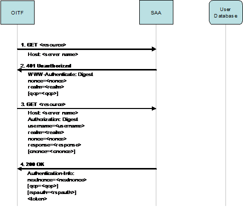
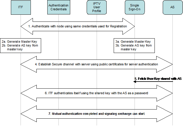
Service Access Authentication: This functional entity is
responsible for service access protection and authentication of users.
The user is identified and authenticated by means of some
pre-established credentials (such as user name and password or GBA
authentication).
Authentication and Session Management (Managed Network Model only):
This functional entity is responsible for the authentication of the
user for service access protection, as well as session management for
the purpose of coordinating and managing (service accessibility) users’
activities and for charging purposes. To this end, the session
management ensures that a user request for a service is routed to the
appropriate Application Server. This entity has access to the
Subscription Profile.
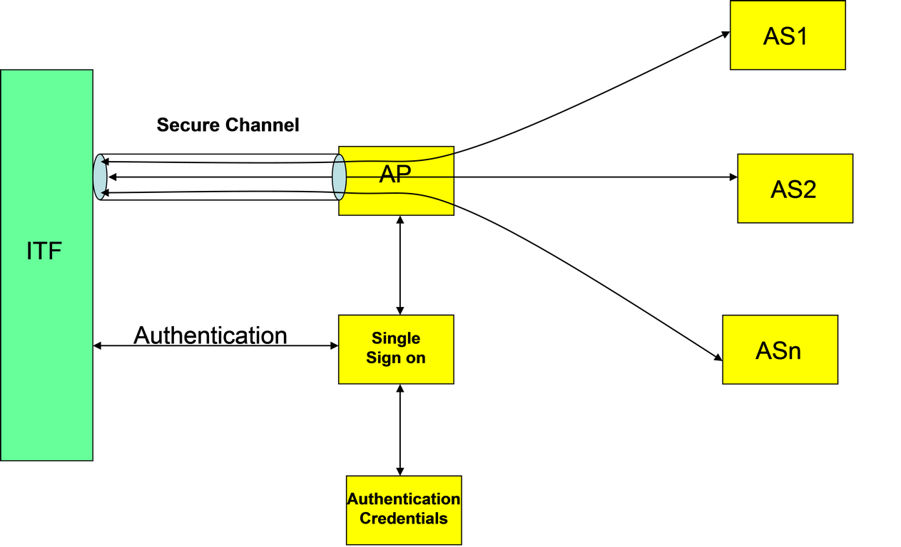
Authentication Proxy (Managed Network Model only): This
functional entity establishes a secure communications channel between a
network provider’s security domain and the ITF. The Authentication Proxy
terminates all signalling and control traffic destined to functions
within the control of the network provider, and eliminates the need for
separate security associations with individual network elements hosting
these functions.
GBA Single Sign-on: This functional entity allows Single
Sign-on based on the Generic Bootstrapping Architecture. It is used in
managed networks, but can also be used in unmanaged networks when a
UICC-based IMS authentication is available in the home network.
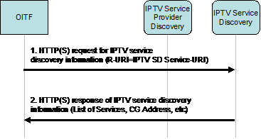
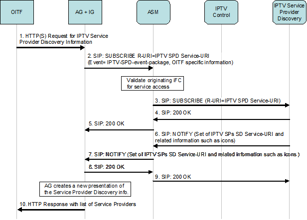
IPTV Service Provider Discovery: provides information necessary for the ITF to select IPTV Service Providers, in both the managed and unmanaged models
IPTV Service Discovery: provides information about IPTV services offered by an IPTV service provider, in both the managed and unmanaged models
IPTV Control: This is the main control point for the
IPTV solution. It controls the delivery of IPTV services to authorized
users. In that regard, it inter-works with the Authentication and
Session Management functional entity, which routes incoming/outgoing
requests from the IPTV Control to the appropriate destination. This
entity has access to the IPTV User and Subscription Profiles. The IPTV
Control generates charging related information.
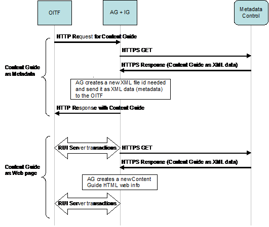
IPTV Metadata Control: This functional entity performs
aggregation of the metadata coming from content providers or third party
sources. The IPTV Metadata Control offers basic metadata related to
services such as service description, the whole program guide, details
related to each event (e.g. description of the film, actors, etc.),
program listings and their schedule, personalized Content Guide (CG).
This functional entity enables the user to search, discover and initiate
immediate viewing or scheduled viewing of future programs and stored
content.
IPTV Applications: These include IPTV related services
or application logic such as CoD, Push CoD, Content Download, Network
PVR, and Messaging as well as Web push/pull service. The function
provides end users with IPTV applications using the Declarative
Application Environment (DAE). The function provides Web Server
functionality to allow an authorized user to access some IPTV services
(e.g., to remotely schedule a recording on a PVR by using a non-OITF
enabled device which has a browser.).
Provider Specific Applications: This function interacts
with the Application Gateway in the consumer domain in order to download
generic applications. Provider specific applications run on the AG
execution environment. The download can be via push or pull mechanisms.
For IPTV, this function can provide end users with provider-specific
applications that run in the Procedural Application Environment (PAE)
which can manipulate media streams and the Content Guide.
Person-to-Person Communication Enablers (Managed Network Model only):
These include interface to various communication services, such as
multimedia telephony, presence, chat, messaging, caller ID notification,
etc., for service blending with IPTV related services.
IPTV Service Profile: This functional entity holds the
IPTV User Profile that is associated with the user’s IPTV subscription
with an IPTV Service Provider. The IPTV User Profile is consulted by the
IPTV Service Provider when the user requests an IPTV service. The IPTV
User Profile can be updated by the IPTV Service Provider as well as by
an authorized end-user, if allowed by the IPTV Service Provider.
User Database: The central database of Subscription
profiles, managed by the Service Platform Provider. The nature of this
may vary between managed and unmanaged systems, and would typically
includes data that is not IPTV service specific such as authentication
information, communication related information, etc.
The Content Delivery Network (CDN): This is a
fundamental functionality in an IPTV CoD solution. For CoD, it allows
the optimization of the network use through a distribution of the media
servers in the physical network, and the optimization of the storage
resources through a popularity-based distribution of the content on the
media servers. This results in having popular content massively
distributed on media servers at the edge of the network (as close as
possible to the customer) while less popular content are distributed on a
reduced number of media servers. For scheduled content, it enables the
support of enhanced services like Personal Channel (PCh) and Network
Personal Recording (nPVR).
Multicast Content Delivery Function: This entity is
responsible for delivery of content and generic data to the OITF by
means of multicast, using multicast streams and the multicast data
channel respectively. In the content streaming case, this is the
so-called head end. In the data case it is the source of the multicast
data channel.
Fast Channel Change/Retransmission Server: The
functional entity that delivers ancillary data for multicast streams
when triggered by the OITF, in the context of FCC/RET service
Network Attachment: This functional entity includes the
functions associated with provisioning of IP addresses, network level
user authentication and access network configuration. For the unmanaged
model, this function is provided by the user’s access network provider.
Transport Processing Function: This functional entity
includes the functions needed to support real-time multicast and unicast
streams, optimizing network usage in the physical network, and
enforcing related traffic policies coming from Resource and Admission
Control.
Resource and Admission Control (Managed Network Model only):
In a managed network, Resource and Admission Control provides policy
control and resource reservation for the required transport resources,
for both unicast and multicast delivery. In this capacity, it interacts
with the authentication and session management functional entity and the
Transport processing function.
Charging: This functional entity includes the charging
mechanisms at the platform level available to all the IPTV Service
Providers, for all the users managed by the Service Platform Provider.
The charging subsystem collects network and platform related events that
can be later used for billing and statistical analysis purposes. The
IPTV service providers are free to build their own billing systems that
could be based on common charging but also be completely independent
(e.g. based on the CSP and CAS). The IPTV service provider’s billing
mechanisms are out of the scope of this specification.
CSP-T Server: This functional entity handles service
protection and content protection for the CSP-T client in the OITF. It
is used to enable the key management necessary to implement service
protection and content protection.
CSP-G Server: This functional entity handles service
protection and content protection for the Content and Service Protection
Gateway (CSPG) in the residential network. The solution for service and
content protection is specific to the IPTV service provider. Therefore,
network reference points are not specified by this specification and
interfaces are defined by the IPTV Service Provider.
Remote Management: In a managed network, this entity
provides the server-side functionalities to remotely manage the
residential network devices, for both provisioning and assurance
purposes: the functions provided relates to configuration management
(including firmware upgrade), fault management (including
troubleshooting and diagnostics), and performance monitoring.
Key Management Function: Entity responsible for storing and providing Service, Program, Content Keys and ECM attached information.
Content on Demand Encryption Management Function: Back office Content on Demand function in charge of encrypting Content on Demand.
Notification Services: This is the server that generates
notifications for end-users in a form that corresponds to the IPTV
end-user preference. The forms currently supported are short message
services (SMS), multi media messaging (MMS), and IMS instant messaging.
Note that these notifications are not related to the DAE-based
notifications on UNIS-6.
Emergency Services: This is the node that generates
emergency messages destined for IPTV end users. This node is not owned
by the platform service provider. Platform service providers just
interfaces with it based on applicable standards which are typically
regional and local in nature.
Messaging AS: This is the server that supports the
generation and delivery of IMS instant messaging to IMS end users. This
is a part of the person-to-person communication enabler but has been
extracted here for clarity.
Other Delivery Networks: This entity represents existing mobile networks used to deliver MMS and SMS messages to end users.
Audience Research Collector: This entity enables the
Service Provider to collect and retrieve Audience Research data by
exploiting the Transport Processing Function to intercept requests from
users. How the Transport Processing Function supports this is out of
scope of this specification. It also enables the Service Provider to
retrieve and collect the Audience Research data from functional entities
such as the IPTV Control, Cluster Controller, IPTV Application, etc.,
as well as other functional entities that receive service status
information through the (SIP/RTSP) signalling path
Audience Research Agency: This functional entity
collects audience research data from different Service Providers, under
the explicit consent of the users. It is usually managed by an external
certified authority, which collects audience data across networks,
platforms, types of services and service providers. It can use the
collected Audience Research data for consultation purposes, or
statistical analysis, data profiling etc. The behaviour of Audience
Research Agency is out of scope of this specification.
Content Management Function: This offline entity handles
content lifecycle (ingest, encoding, encryption, distribution) and
content aggregation into commercial offers for On-Demand Content.
Scheduling Function: This offline entity handles content
lifecycle (ingest, encoding, encryption, distribution) and content
aggregation into commercial offers for Scheduled Content.
Scheduled Content Encryption Function: Back office Scheduled Content function in charge of encrypting the Scheduled Content.
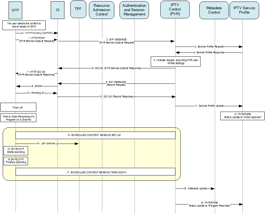
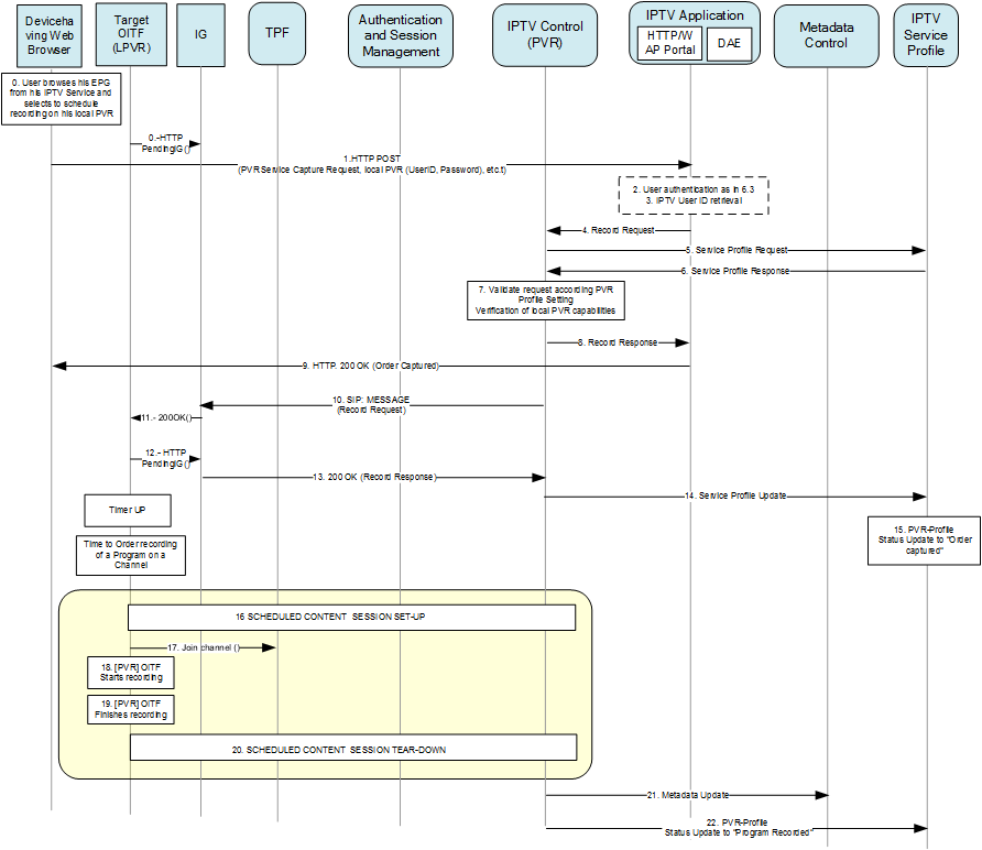
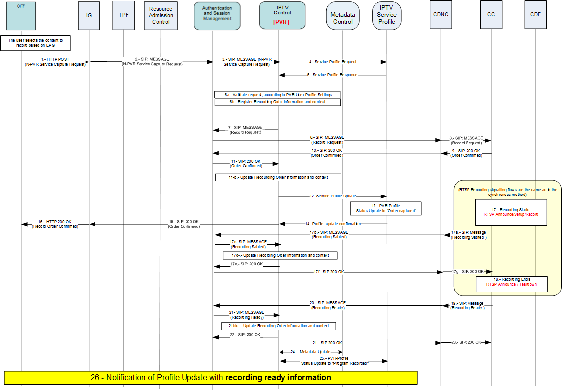
Recording Function: This function handles the recording of Scheduled Content for later use for catch-up and start-over.
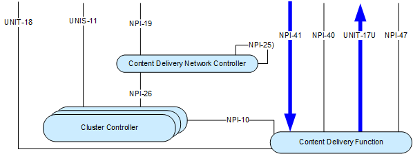
5.2.1.1 Content Delivery Network
The following section describes the internal functional entities and reference points in the CDN functional entity.
Figure 5-3: CDN Architecture
The following is a brief description of the functional entities that make up the CDN, as depicted in Figure 5-3.
The Content Delivery Network contains three sub-functions:
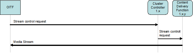
Content Delivery Network Controller (CDNC): This functional entity performs cluster The
term Cluster corresponds to a logical association of one or more
"Content Delivery Functions" which share some resources (such as
location, storage capacity etc.). selection in the CDN, based on
the request issued by the IPTV Control functional entity. Many
instances of a CDN controller may coexist in the same CDN. They may
interact for the purpose of selecting the right cluster.
Cluster Controller (CC): This functional entity manages a set of Content Delivery Functions (a cluster of CDFs).
It terminates IPTV service session setup
It handles content delivery session setup
It proxies all message exchanges between CDFs and the ITF.
It maintains the state of the media servers (Content Delivery Functions)
Content Delivery Function (CDF): This functional entity
is responsible for media processing, delivery and distribution, under
the control of the Cluster Controller.
The following reference points depicted in Figure 5-3 are internal to the CDN:
NPI-10;
NPI-25;
NPI-26;
5.2.2 Mapping between HLA and IPTV Domains (informative)
Table 1 provides an informative mapping between the functional entities depicted in the HLA and the IPTV domains as defined in section 4.1.
Table 1: Functional Entity domain assignment
Functional Entity
Domain Assignment
Network Attachment
Network Provider
Authentication and Session Management (Managed Network Model only)
Service Platform Provider
User Database
Service Platform Provider
IPTV Control
Service Platform Provider
Person to Person Communication Enablers (Managed Network Model only)
Service Platform Provider
IPTV Applications
IPTV Service Provider
Content Delivery Network Controller
Network, Platform and IPTV Service Providers
Content Delivery
Network, Platform and IPTV Service Providers
IPTV Metadata Control
IPTV Service Provider
IPTV Service Discovery
Service Platform Provider, IPTV Service Provider
IPTV Service Provider Discovery
Service Platform Provider
IPTV Service Profile
IPTV Service Provider
Provider Specific Applications
IPTV Service Provider
Multicast Content Delivery Function
Network, Platform and IPTV Service Providers
Metadata Storage
IPTV Service Provider
Service Access Authentication
Service Platform Provider
Charging
Service Platform Provider
Cluster Controller
Network, Platform and IPTV Service Providers
Resource and Admission Control (Managed Network Model only)
Network Provider
Transport Processing Function
Network Provider
Authentication Proxy (Managed Network Model only)
Service Platform Provider
GBA Single Sign-on
Service Platform Provider
CSP-T Server
IPTV Service and Service Platform Provider
CSP-G Server
IPTV Service and Service Platform Provider
Content and Service Key Management Function
IPTV Service Provider
Content-on-Demand Encryption Management Function
IPTV Service Provider
RMS
Network Provider, Service Platform Providers
Notification Services
Service Platform Provider
Emergency Services
Law enforcement agencies
Messaging AS
Service Platform Provider
Other delivery networks
Service Platform Provider
5.2.3 Reference Points Description
5.2.3.1 UNI Reference Points
The UNI is expressed as several reference points, each of which map
to the various functional entities required to provide the necessary
support for the end-to-end IPTV service. The notation used to identify
the reference points of the UNI, as well as a detailed description for
all the reference points, is described later.
Table 2: UNI Reference Points
Reference Point
Description
UNIP-1
Reference point for user initiated IPTV User Profile management
UNIP-2
Reference point for user initiated profile
management of Person-to-Person Communication Enablers, such as presence
privacy, resource list management, group management, etc.
Note that group management is included to support the management of
pre-defined groups that can be reused for several purposes, such as
presence privacy, presence request, messaging, chatting, etc.
UNIS-6
Reference point for user interaction with
application logic for transfer of user requests and interactive feedback
of user responses (provider specific GUI). HTTP and TCP based
application-specific protocols are used to interface between the DAE and
the IPTV Application Function.
UNIS-7
Requests for transport and encoding of content
guide metadata. The reference point includes the metadata and the
protocols used to deliver the metadata, and shall be based on DVB-IP
BCG. [Ref-13]
UNIS-8
Authentication and session management relying on IMS.
UNIS-9
Authentication for GBA Single Sign-on
UNIS-11
Reference point for control of real time
streaming (e.g. control for pause, rewind, skip forward). This reference
point is optionally secured. The reference point includes content
delivery session setup when not relying on IMS.
UNIS-12
Reference point between the AG (see section 5.3.1.3 for details) and the provider specific application functional entity. Encompasses two functions:
Signalling and download of applications in a generic format. (Subject to standardization)
Interaction of generic applications with the provider network. (Not subject to standardization)
UNIS-13
User Stream control for multicast of real time content and data. The protocol used on this interface is IGMP. [Ref-10]
UNIS-14
Reference point used for authorization of service access.
UNIS-15
Reference point to the IPTV Service Discovery FE to obtain information about IPTV services offered by an IPTV Service Provider
UNIT-16
Network attachment functions connected to this reference point include: DHCP Server and Relay.
UNIT-17
Content stream including content; content
encryption (for protected services) and content encoding. This
reference point can be used for both multicast and unicast (UNIT-17M and
UNIT-17U, respectively). This could be RTP and HTTP (unicast only). It
includes the FCC/RET RTP packets issued by the FCC/RET server. It can
also be used for bidirectional RTP-based transfer of voice and real-time
video with predefined formats, i.e., media to support conversational
multimedia communications.
UNIT-18
Performance monitoring interface for reporting
the performance monitoring results. A possible protocol is RTCP. This
interface is also used for RTCP control interaction to and from the
FCC/RET server
UNIT-19
Multicast Data Channel. Used to deliver data of
different kinds to the OITF by means of multicast. This reference point
can carry discrete data that is carried over unicast through e.g. the
interfaces UNIS-6, and UNIS-7. Other uses e.g. UNI-RMS are not excluded.
UNIS-19
Reference point to the IPTV Service Provider
Discovery functional entity to obtain the list of Service Providers, and
related information.
UNI-RMS
Remote Management of end user devices (based on the DSL Forum TR-069 [Ref-1] framework and related extensions based on DVB-IP-RMS specification)
UNIS-CSP-T
Rights management for protected content – including key management and rights expression.
UNIS-CSP-G
Reference point to support a service and
content protection solution which is specific to IPTV Service Provider.
This interface may be used to obtain licenses for purchased/subscribed
content, control content and service protection system and also deliver
content.
5.2.3.2 Network Reference Points Description
Table 3: Network Reference Points
Reference Point
Description
NPI-1
Reference point between the Service Access Authentication FE and the User Database.
NPI-2
An optional reference point allowing interaction
between IPTV Applications and the IPTV Control FE. This is not subject
to standardization.
NPI-3
The reference point between Authentication Session
Management and Person-to-Person Communication Enablers. (This is the
ISC interface defined by 3GPP) [Ref-15]
NPI-4
Reference point for routing of IPTV service
related messages to the IPTV Control Point. This is the ISC reference
point defined by 3GPP [Ref-15].
NPI-6
This reference point allows the IPTV Control Point
to retrieve the subscriber’s IPTV-related service data when a user
registers in the IMS network. (Not subject to standardization)
NPI-7
This reference point allows Person-to-Person
Application Enablers to retrieve the subscriber’s IMS data from the User
Database. This is the Sh interface defined by 3GPP [Ref-15].
NPI-9
This reference point allows the IPTV Control Point
to retrieve the subscriber’s IMS-specific data from the User Database.
This is the Sh interface defined by 3GPP [Ref-15].
NPI-10
An optional reference point for the
allocation/de-allocation and control of content for a specific unicast
session. This reference point is internal to the CDN.
NPI-11
A reference point for sending events and charging information. This is the Rf reference point defined by 3GPP [Ref-15].
NPI-12
This reference point allows the Authentication
and Session Management FE to retrieve the subscriber’s IMS data from the
User Database as a part of the user’s IMS registration. This is the Cx
interface defined by 3GPP [Ref-15].
NPI-14
Same as NPI-11
NPI-15
This reference point controls the Resources and Admission Control. It is the Gq’ interface defined by ETSI TISPAN. [Ref-15]
NPI-16
Reference point between the Transport Processing
Function and Resource and Admission Control. It is the Re interface
(Diameter based) [Ref-15]
NPI-17
Reference point between the IPTV Applications and the IPTV Service Profile.
NPI-18
Reference point between the Service Access and Authentication FE and the IPTV Applications.
NPI-19
This reference point is used for unicast session
control between the Authentication and Session Management and the
Content Delivery Network Controller
NPI-20
This optional reference point allows the retrieval of CG data. (Not subject to standardization)
NPI-21
This reference point allows the GBA Single Sign-on functional entity to validate user credentials
NPI-25
This reference point allows proxying unicast
control messages to locate the appropriate Content Delivery Network
Controller FE. This reference point is internal to the CDN.
NPI-26
The reference point allows the Content Delivery
Network Controller to delegate the handling of a unicast session to a
specific Cluster Controller. This reference point is internal to the
CDN.
NPI-27
The reference point between the Authentication
Proxy and the GBA Single Sign-on node allows the proxy to retrieve a
user key for authentication purposes.
NPI-28
This reference point is used to push the user
access capabilities to the Network Attachment and the RAC. This is the
e4 interface defined by 3GPP [Ref-15].
NPI-30
This reference point supports the IPTV Service
Provider Discovery step of the service discovery procedure relying on
IMS. This is the ISC interface defined by 3GPP [Ref-15].
NPI-32
Reference point between the ASM FE and the IMS messaging AS. (This is the ISC interface defined by 3GPP) [Ref-15]
NPI-33
Reference point allowing interaction between IPTV
Applications and the IPTV Metadata Control FE. This is not subject to
standardization.
NPI-34
The reference point between the IMS messaging
server and the notification services. It is based on IMS SIP as defined
in 24.229 [Ref-18]
NPI-36
This reference points allows access to
notification services. It is based on Parlay X -API as defined by
(http://www.3gpp.org/ftp/Specs/html-info/29-series.htm).
This reference point between notification
services and multicast and delivery control function supports multicast
traffic for emergency services and is FFS.
NPI-39
This reference point between emergency services and the notification services is local and regional specific.
NPI-40
Content Delivery Function (CDF) Stream control for multicast of real time content. The protocol used on this interface is IGMP [Ref-10]. This interface is optional.
NPI-41
Content stream including content; content
encryption (for protected services) and content encoding. This
reference point is used for multicast delivery. The protocol used on
this interface is RTP. This interface is optional.
NPI-42
This reference point between the IPTV Application
and the Multicast Content Delivery Function supports multicast traffic
for notification services.
NPI-CSPT1
Reference point to confirm whether a Marlin content license can be issued for the request received via UNIS CSP-T.
NPI-CSPG1
Reference point to allow the CSP-G Server to be provisioned with entitlement information by IPTV Applications.
NPI-CSPG1a
Reference point to allow the CSP-G Server to be provisioned with entitlement information by the IPTV Service Profile.
NPI-CSPG3
Reference point for the Key Management Function to exchange content encryption information with CSP-G Server.
NPI-CSPT1a
Reference point used by the Marlin DRM system
to include business information or a reference to business information
into a DRM request (e.g. license request) as requested via UNIS-CSP-T,
and the subsequent confirmation and retrieval of this business
information when the DRM request is consumed.
NPI-CSPT2
Reference point, used in the managed network
model, to retrieve information on the appropriate cluster controller in
the Content Delivery Network that will serve a particular request for
purchased or subscribed-to content. This chosen cluster controller will
be contacted by the CSP-T Server functional entity via NPI-CSP3. This
interface is not specified by this version of the specification.
NPI-CSPT3
Reference point to retrieve the appropriate
encryption key needed to prepare a Marlin content license for the chosen
content. It is the content encryption key for downloadable content or
the key that encodes the Marlin short term key message that contains the
key that encodes the streaming media.
NPI-43
Reference point that provides GBA authentication mechanism to the Service Access Authentication Function.
NPI-44
Reference point where the encrypted content is
stored on the content storage entity for delivery by the Content
Delivery Function. This interface is not specified by this version of
the specification. This interface has been identified just to illustrate
informatively the separation between content encryption, which is part
of content preparation, and content delivery.
NPI-45
Reference point where the content Service,
Program and Content Keys and ECM attached information are provided to
the CoD Encryption Management Function.
NPI-46
Reference point where the content Service,
Program and Content Keys and content protection related information
(e.g. ECM, DRM metadata) are provided to the Scheduled Content
Encryption Function. This interface is specified by this version of the
specification for the unicast stream encryption case. This interface is
not specified by this version of the specification for the multicast
stream encryption case.
NPI-47
Reference point where the On Demand Content is
fetched by the Content Delivery Function for delivery. This interface is
not specified by this version of the specification. This interface has
been identified just to illustrate informatively the separation between
content encryption, which is part of content preparation, and content
delivery.
NPI-48
Reference point for the Key Management Function
to provide appropriate information to the IPTV Applications functional
entity, e.g. in relation with content access licenses. This interface is
not specified by this version of the specification.
NPI-49
Reference point for the Content Management
Function to provide the CoD Encryption Function with content related
information. This interface is not specified by this version of the
specification.
NPI-50
Reference point for the Scheduling Function to
provide the Recording Function with a record list/schedule for the
Catch-up and Start-over use cases. This interface is not specified by
this version of the specification.
NPI-51
Reference point for the Content Management
Function to provide appropriate information to the IPTV Applications
functional entity. This interface is not specified by this version of
the specification.
NPI-52
Reference point for the Scheduling Function to
provide appropriate information to the IPTV Applications functional
entity. This interface is not specified by this version of the
specification.
NPI-53
Reference point for the Scheduling Function to
provide the Scheduled Content Encryption Function with content related
information and schedule. This interface is not specified by this
version of the specification.
NPI-AR-01
Reference point for providing static audience
data about users who have opted-in. It includes content metadata and
user related information stored in the IPTV Service Profile.
NPI-AR-02
NPI-AR-02’
NPI-AR-02’’
Reference points for collecting the information intercepted by the
Transport Processing Function, the IPTV Control, the Cluster Control or
other FEs based on different criteria, e.g. the events triggered by the
Audience Research Collector, event detected from other FEs, the
deployment done by the service provider etc.
Note: The IPTV Control can retrieve the Audience Research data from
the ITF or the Cluster Controller using existing SIP messages such as
SIP INFO, MESSAGE, INVITE or PRESENCE.
NPI-AR-03
Reference point used for exposing the Audience Research data to the Audience Research Agency.
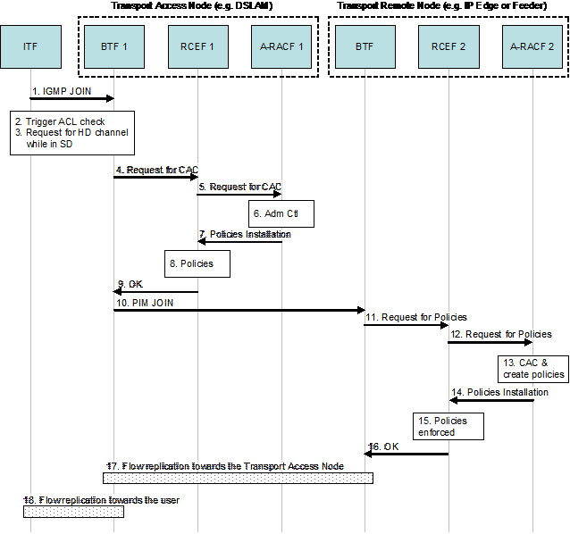
The architecture of the consumer domain (referred to hereafter as the residential network) is as shown in Figure 5-4
and composed of 5 functional entities, with well defined interfaces
between them, and where each functional entity includes a number of
functions. As shown in Figure 5-4, the entire collection of these functional entities is called the IPTV Terminal Function (ITF).
The residential network architecture is designed to:
Support multiple deployment scenarios.
Allow non-IPTV applications to co-exist with IPTV services, but be able to execute independently from the IPTV service.
The architecture chosen to comply with the above is depicted in Figure 5-4 below.
There are two main interface groups between the Residential Network
and the Provider(s) Network domain: the HNI-INI and the HNI-AMNI. The
mapping between these key functional groupings and UNI reference points
is depicted in Figure 5-4.
Note also that, while not shown explicitly in Figure 5-2, all communications are mediated by the WAN gateway.
Figure 5-4: Residential Network Architecture
Below is a brief description of the functional entities in the residential network:
Open IPTV Terminal Functional Entity (OITF)
The OITF includes the functionality required to access IPTV service
for both the unmanaged and the managed network models through the
HNI-INI and HNI-IGI interfaces.
To access the IPTV services using the unmanaged model, the OITF only
needs to use the HNI-INI interface. Thus, the minimum set of functional
entities needed to access unmanaged IPTV services are the OITF and the
WAN Gateway.
To access IPTV service using the managed network model, the
OITF needs to use both the HNI-INI and the HNI-IGI interfaces. Thus, the
minimum set of functional entities needed to access the managed IPTV
services are the OITF, the IG and the WAN Gateway (as it provides the
physical connection between the residential network and the WAN). The
HNI-IGI interface requires special protection, as it carries
credentials/secrets.
The OITF has its own direct user interaction (e.g., remote control,
keyboard) and audio/video rendering and, optionally, grabbing
functionalities (e.g. display, speakers, cameras, microphones) or can be
directly connected with other audio/video rendering/grabbing devices
without passing through home network communication.
All Residential Network deployments will have at least one instance of the OITF.
The OITF may include functions to allow Open IPTV Forum defined services to be accessed on DLNA devices [Ref-2].
IMS Gateway Functional Entity (IG)
The IG includes the necessary functionality to allow an OITF device
to access managed network services, based on an IMS core network,
through the HNI-IGI interface. The IG provides an IPTV end user with
access to managed network IPTV services and to blended person-to-person
communication services such as Chat, Messaging, Presence, etc. Support
for unsolicited notification is also included for such services as
Presence, Caller ID, etc.
The IG is able to offer its functionality to the AG via the HNI-AGI interface.
Support for new or enhanced applications can be realized by a
firmware upgrade to the IG without any impacts on the OITF
functionality.
In a device that implements both the OITF and IG the use of the HNI-IGI interface is optional.
Application Gateway Functional Entity (AG)
The Application Gateway (AG) is an optional gateway function that
incorporates a procedural language based application execution
environment where applications can be remotely downloaded for execution.
This functionality is required by certain service providers that wish
to have generic procedural language based applications related or
unrelated to IPTV services downloaded for execution in the home
environment. Examples of applications related to IPTV services include
an EPG generating a remote UI; proxying for signalling protocols when
not involving SIP, and when client and server are not in same IP domain;
support for proprietary or non-standard content download protocols
(where the AG has A/V content storage capability); insertion of
personalized advertisements in media stream; and full blended
person-to-person communication services (e.g., videoconference using a
TV set as a display). An example of an application unrelated to IPTV
services is one that collects alarms from home devices.
To interface to the AG, an OITF uses the HNI-INI-AG interface. The
HNI-INI-AG is a selection from the reference points in the HNI-INI
interface, in addition to the support for discovery of an AG by an OITF.
When present, the AG, through application running in the executable
application environment, can perform any of the following
functionalities:
Manipulate media streams.
Note that for protected content, this is only addressed when the AG
and the CSPG are combined in the same device and that the Release 2
Solution [Ref-45] does not define the routing of media content (for the purposes of media control) via an AG which is not also a CSPG.
Filter Content Guide (CG) data; insert its own CG data.
Note that in the Release 2 Solution [Ref-45],
this is only addressed where the resulting content guide is output from
the AG to the OITF in the form of a remote UI. The Release 2 Solution
does not define how an AG may output CG data in Broadcast Content Guide
(BCG) format to an OITF, or how an OITF may discover that BCG format
information is available from an AG.
Support proprietary applications through a Remote User Interface (RUI).
Support for proprietary or non-standard content download protocols
Support advanced blended communication services.
When the AG is deployed in a device with local graphics rendering
(e.g. combined with an OITF), applications running in the PAE can offer a
wide range of applications and services directly using that local
graphics rendering system without using a remote UI.
The AG is able to make use of the services of the IG via the HNI-AGI
interface. This interface is not defined in the Release 2 Solution [Ref-45];
however, where an AG and an OITF are combined in the same device, the
device may use the HNI-IGI interface for both DAE and PAE applications.
Content and Service Protection (CSP) Gateway Functional Entity (CSPG)
The CSP Gateway (CSPG) is an optional gateway functional entity that
provides a conversion from a content and service protection solution in
the network to a secure authenticated channel between the CSPG and the
OITF.
WAN Gateway Functional Entity (WG)
The WAN Gateway function supports the physical connection between the
residential LAN and the Access Network WAN. A WAN gateway functional
entity will exist in all deployments although not all its functions will
be required in all cases.
5.3.1 Residential Network Functional Entities
The following is a more detailed description of the various functional entities identified above.
For ease of understanding of the detailed functional description of
the residential network, this specification uses a stepwise build up of
the residential network functional entities comprising of the following
steps:
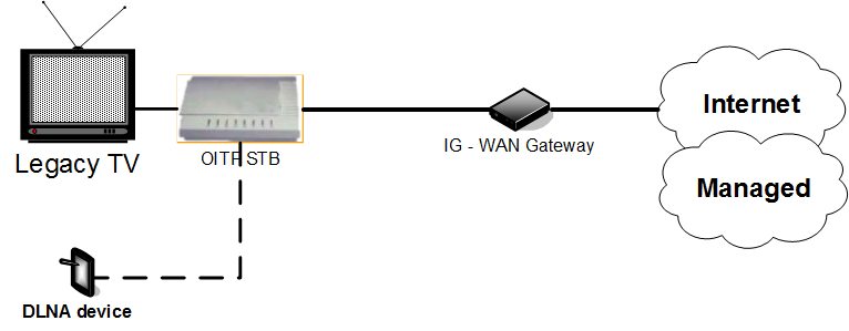
OITF and WAN Gateway (WG)
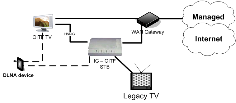
OITF, WG and IG
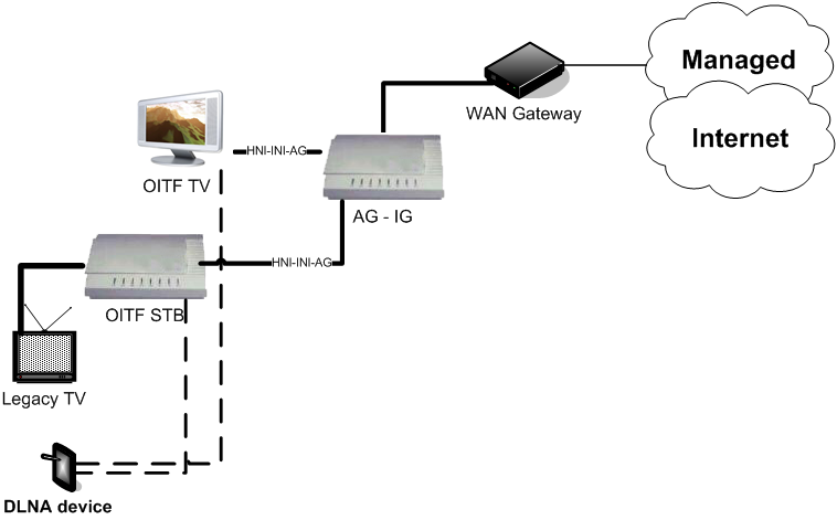
OITF, WG, IG and the optional functional entities AG and CSPG
Note that this build-up of functions does not imply that these
combinations of functions are the only deployment options possible. Each
of OITF, IG, AG, CSPG and WAN Gateway functional entities may be
deployed as separate physical devices in the residential network or in
combinations or may not be deployed at all in the case of the optional
entities AG and CSPG as described in section 5.3.4.
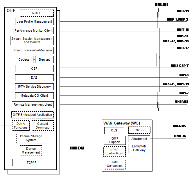
5.3.1.1 Open IPTV Terminal Functional Entity (OITF)
Figure 5-5: OITF functions and interfaces exposed
The OITF functional entity shown in Figure 5-5 includes the following functions:
User Profile Management: Manages subscription information
associated with a specific User, e.g., viewing preferences. The user
profile management functions include the ability to create, fetch,
modify, delete, replace user profiles.
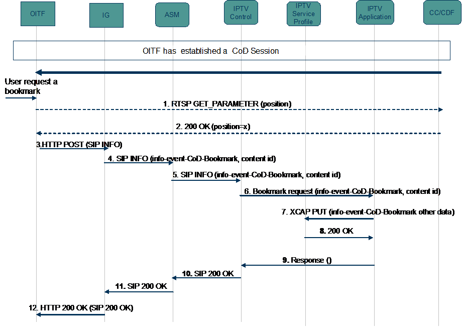
Stream Session Management and Control: Initiates and
terminates content delivery sessions. Manages content delivery sessions,
including trick play control of unicast streams and multicast stream
control. It applies to both the unmanaged and the managed models.
Stream Transmitter/Receiver: Receives streamed content from
the network and includes stream buffering in the case of progressive
download. It also transmits real-time audio and video in the case of
multimedia telephony. The function applies to both the managed and
unmanaged models, although different technologies might be chosen for
each case.
Codecs: A/V codecs for all streamed and downloaded content. It includes decoding, scaling and rendering functions.
CSP: Client side key management for the terminal centric
approach to service protection and content protection. Enforces content
usage rules in the client. It applies to both the managed and the
unmanaged models. See CSP Gateway functional entity for the alternative
gateway centric approach to service and content protection.
Content Download: Reception of content downloaded to the
client in non-real time. Content download might be unicast or multicast.
For multicast, the MDTF is used. Local storage is required for content
download. It applies to both the managed and the unmanaged models. This
function is optional.
MDTF (Multicast Data Terminating Function): This function
receives generic data sent over multicast. Content types that can be
distributed to MDTF include Content Guide data, static DAE content,
video content, interactivity information, notifications, software
releases and patches.
Decrypt: Removes any encryption applied to the content, under
the control of the CSP function. This function is not used for
unencrypted content. It applies to both the managed and the unmanaged
models.
Declarative Application Environment (DAE): A declarative language based environment (browser) based on CEA-2014 [Ref-3]
for presentation of user interface and including scripting support for
interaction with network server-side applications and access to the APIs
of the other OITF functions.
The specification of the DAE declarative language environment
including the APIs available to the downloaded applications is within
the scope of the Forum.
The DAE can also query, internally to the OITF, the Metadata-based
Content Guide Client in order to extract any data it may contain.
The downloaded applications that run in the DAE are considered to be
Service Provider specific and therefore will not be defined by the
Forum’s specifications.
Metadata-based Content Guide Client: Client for metadata-based
content guides. The user interface including the presentation of
metadata-based content guide is OITF vendor dependent and is out of
scope of this specification. This function may also make the metadata
available to Residential Network devices via the DLNA Functions
function. It applies to both the managed and the unmanaged models.
Remote Management Client: provides the client-side functions
to remotely manage the OITF, for both provisioning and assurance
purposes. The functions provided relate to configuration management
(including firmware upgrade) and fault management (including
troubleshooting and diagnostics). When realized as standard TR-069
client, it uses the UNI-RMS interface (providing also performance
monitoring); otherwise, remote management is supported as a DAE
application which uses the UNIS-6 interface.
IPTV Service Discovery: Function for discovering IPTV Service
Providers and related services. It applies to both the unmanaged and
the managed models. Note that different aspects of DVB SD&S [Ref-4] may apply to the different models.
Integral Storage System: Storage for content download and PVR
based functions. This function is optional but will be required if
Content Download is supported.
DLNA Functions: Implements DLNA DMS [Ref-2]
functions to expose and distribute content in a DLNA compliant manner
through the residential network. The DLNA Functions function may also
offer a DLNA DMP [Ref-3]
function to locate and select content available from other DMS in the
residential network. The selected content can be streamed across the
residential network and rendered by the OITF. The DLNA Functions may
also support the DLNA RUI Source capability (+RUISRC+) to provide remote
UI content to the DLNA RUI Pull controller capability (+RUIPL+), which
can be used to support an ITF Remote Control Function (IRCF). This
function is optional.
OITF embedded application: This optional function provides
embedded applications for IPTV services, e.g. local PVR, using the
standardized interfaces which are defined as UNI and HNI-IGI. The user
interaction with this function is OITF vendor specific
Performance Monitor Client: Client for providing feedback on
service quality – for example, pixilation, frame loss, packet loss and
delay (the exact information to be provided is to be specified other
specifications). It applies to both the managed and the unmanaged
models.
Device Management: This function acts as a UPnP Device Management Client [Ref-42]
for remote management operations such as configuration management
(including triggering of a software upgrade) and fault management
(including troubleshooting and diagnostics).
The WAN Gateway functional entity shown in Figure 5-5 contains the following functions:
LAN/WAN Gateway: Supports the physical termination of the
access network (e.g. xDSL, GPON etc.) and the layer 2, layer 3 and
higher services (such as NAT, IGMP proxy-routing) required to support
IPTV and other services terminated in the residential network that share
the WAN connection.
Attachment: Attachment function is responsible for the attachment of the residential network to the Network Provider.
RMS3: Depending on the provider model, the WAN Gateway may be
remotely monitored and configured by the access service provider. The
RMS function supports the interface to the remote manager (i.e. TR 069
CWMP remote management protocol [Ref-1], plus TR 098 device data model [Ref-33] with possible extensions.)
QoS: The QoS function provides classification, marking,
re-marking, policing, and queuing of Ethernet and IP traffic that goes
between the WAN and LAN interfaces. Marking and re-marking of Ethernet
priority and Diffserv code points (DSCP) [Ref-6]
is supported. Classification can occur through a variety of
characteristics of IP traffic, including Ethernet priority, DSCP,
origination and destination IP address, and application protocol.
IGMP Support: Provides the functions for IGMP Proxy and IGMP
Snooping. The IGMP Proxy allows multiple in-home devices in the
residential network to be able to join the same multicast stream. IGMP
Snooping is the process of listening to IGMP traffic to allow, when
present, the switch to "listen in" on the IGMP conversation between
hosts and routers by processing the layer 3 IGMP packets sent in a
multicast network to avoid flooding (see section 5.3.3.1).
UN/MC Conv: The WAN Gateway may have this function to avoid
some problems due to the low efficiency and unreliability of multicast
on wireless networks. This function is not specified in the Release 2
Solution [Ref-45].
UPnP Control Point: The UPnP Control Point [Ref-28] interacts with the UPnP Device Management Client [Ref-42] in the OITF for remote management operations.
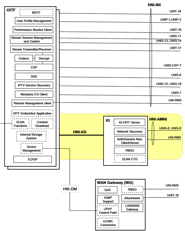
5.3.1.2 OITF and IG
Figure 5-6: OITF and IG
In a device that implements both the OITF and IG, the use of the HNI-IGI interface is optional.
The IG functional entity depicted in Figure 5-6 includes the following additional functions:
IMS Gateway (IG)
Authentication/Session Management Client/Server: Responsible
for subscriber authentication and any session management required for
managed networks (e.g., managed IPTV services and person-to-person
communication services). The authentication performed by this function
is (re-)used for Content and Service Protection (CSP) purposes.
The Authentication/Session Management client/server interacts with
the network servers through the UNIS-8 interface. This function includes
the implicit connectivity admission control (CAC) request for the WAN
side. No explicit CAC function is required on the LAN side.
IG-OITF Server: The IG-OITF server exposes authentication and
session management client/server functionalities to the OITF for
managed IPTV services and blended person-to-person communication
application support (e.g., caller id display, messaging etc.) via HTTP
and/or other protocols as required. If required, the interaction between
the IG-OITF Server and the OITF may result in a UI on the OITF display
or the delivery of execution script(s) to the DAE function on the OITF.
RMS2: Client application for remote management functions in a
managed environment. It provides a standard interface for provisioning
and assurance tasks on managed devices with the IG function (i.e. TR 069
CWMP remote management protocol [Ref-1], plus TR 104 [Ref-29]
IMS data model with possible extensions). It includes functions for
configuration management, firmware upgrade, troubleshooting/diagnostics,
performance management and monitoring of IMS/SIP services.
Network Discovery: Network discovery function is responsible for the discovery of and attachment to an IMS service provider.
DLNA Content Transformation Device (DLNA CTD): This optional
function provides media transformation, e.g. transcoding for remote
access. The DLNA Content Transformation Device implements the DLNA Media
Interoperability Unit (MUI) device class or DLNA devices which
implement the DLNA virtual device functionality with content
transformation function.
5.3.1.3 OITF, IG, AG and CSPG
Figure 5-7: All Residential Network Functional entities
A residential network with the addition of the optional Application
Gateway and the optional CSP Gateway functional entities is depicted in
Figure 5-7.
This represents a residential network with all the residential network
functional entities. The AG and CSPG are independent optional functional
entities that may be required in a specific residential network
configuration. The following additional functions are identified.
Application Gateway (AG)
Procedural Application Environment (PAE): A local procedural language execution environment based on Java Connected Device Configuration (CDC) [Ref-34]
for IPTV Service Provider specific downloaded applications. If
required, these applications can present a UI via the CEA-2014 [Ref-2]
based Remote UI function on the OITF’s DAE. When the PAE is deployed in
a device with local graphics rendering (e.g., combined with an OITF),
these applications also can also directly access that local graphics
system.
The definition of the full capabilities of the PAE is within the
scope of the Forum’s specifications. The specification of the Service
Provider specific applications that are downloaded and executed in the
environment are outside of the scope of the Forum’s specifications.
The PAE is a multipurpose execution environment capable of supporting
many IPTV-specific and general services. These capabilities include
support of the following service provider specific applications:
Media Control: Enables the Service Provider to locally
intercept the media stream (media, control, CSP) for the purpose of
adding or inserting content generated or stored in the AG into that
media stream. The operation of Media Control shall be under the control
of Applications running in the PAE via defined APIs.
Note that for protected content, this is only possible when the AG
and the CSPG are combined in the same device and that the Release 2
Solution [Ref-45] does not define the routing of media content (for the purposes of media control) via an AG which is not also a CSPG
CG: Client with the following functions:
Discovery and description of available services and content.
At least one of:
Presentation of an CG on the OITF via the DAE
Passing all or some subset of the metadata to the “Metadata CG
client” on the OITF, depending on the policy of either the Service
Platform Provider or the IPTV Service Provider.
Note that this is not addressed in the Release 2 specifications.
When present, this application terminates the UNIS-7 interface
in addition to the CG application client in the OITF, which also
directly handles the UNIS-7 interface.
IPTV Service Discovery: Client with the following functions:
Discovery of available service providers.
Discovery and description of available services and content.
Fully blended communication services: Possibly requiring
additional hardware to support advanced applications such as video
telephony. The HNI-AGI interface allow applications in the AG
implementing advanced communication services to access the Authorization
and Session Management functions in the IG.
RUI Server: This function enables applications running
in the PAE to serve declarative language applications running on the DAE
in the OITF.
Proprietary or non-standard content download protocols: Implementation of proprietary, non-standard or other service provider-specific protocols in a PAE application.
RMS1: Client application for remote management functions in a
managed environment. It provides a standard interface for provisioning
and assurance tasks on managed devices with the AG function (i.e. TR 069
CWMP remote management protocol [Ref-1], plus TR 135 [Ref-30]/TR 140 [Ref-31]
IPTV/storage data model with possible extensions). It includes
functions for configuration management, firmware upgrade,
troubleshooting/diagnostics, performance management and monitoring of
streaming services.
CSP Gateway (CSPG)
The CSP Gateway is required when a gateway centric approach to
service and content protection is deployed as an alternative to the
Marlin based CSP functions of the OITF. A secure authenticated channel
is used between the CSPG and the OITF.
5.3.2 Handling QoS in the Residential Network
The QoS function in the WAN gateway is responsible for the QoS
marking (e.g., DSCP, Ethernet priority) into and out of the residential
network. All nodes in the residential network are responsible for
marking the appropriate priority of originating traffic.
5.3.3 Multicast Handling in modem gateway router
Modem gateway router includes transport related functionality such as
LAN handling, IP multicast support, etc. IPTV services require
additional functionality to be supported in order to ensure efficiency
in the home LAN environment.
5.3.3.1 Multicast and the Home LAN
It is expected that scheduled content services will use IP multicast
technology to deliver A/V streams. Although IP multicast is efficient in
the Network Provider domain, it will cause some issues in Residential
network environment, such as
Flooding to unnecessary segments
Gateway routers broadcast incoming multicast packets to all ports,
resulting in unnecessary packets being delivered to endpoints that are
not listeners for that or any multicast stream, and must discard them.
This situation is depicted in Figure 5-8.
Figure 5-8: Example of flooding issue
IGMP snooping in the switching function of the home gateway router
will solve this issue to some extent. But if there is a secondary switch
in the residential network which does not support IGMP snooping, the
same issue still remains, although its severity has been reduced.
Low efficiency and unreliability of multicast on Wireless networks (802.11 WLAN) [Ref-7]
Multicast frames can not be transmitted at as high a rate as unicast
frames. Also, the reliability of multicast is low due to the lack of
retransmission mechanisms in Layer 2.
To remedy this problem, it is necessary to perform multicast to
unicast conversion at the home entry point. The conversion will be done
at Layer 2 or Layer 3 by snooping IGMP messages [Ref-8] and managing the membership of multicast listeners.
In this release of the architecture, support of IGMP snooping and IGMP proxy [Ref-9] is mandatory to avoid flooding of unnecessary segments.
5.3.3.2 Local Multicast within the Gateway Router
It is mandatory for home routers compliant to this architecture to
support local multicasting to avoid the consumption of any additional
bandwidth in the last mile when multiple end points are watching the
same stream. IGMP snooping can solve that issue by dropping IGMP JOINs
for streams that are already available, and ensuring that these streams
are replicated locally and delivered to these end points.
5.3.4 Deployment Options
This section describes the allowable deployment options in the
residential network, and the services supported by each deployment
option.
Each of the OITF, IG, AG and WG functional entities may be deployed
as separate physical devices in the residential network, or in
combinations as described in this section.
5.3.4.1 Services Available in the Residential Network
Table 4 shows the services available the residential network for each combination of functional entities.
Table 4: Services from Functional Entities
Functional Entities deployed in the residential network
Services available
WG
OITF
IG
AG
X
X
Unmanaged network services only are available. DAE applications can be deployed.
X
X
X
Managed network and unmanaged network services are available. DAE applications can be deployed.
X
X
X
X
Managed network and unmanaged network services are available. DAE and PAE applications can be deployed.
X
X
X
[This deployment option is not defined by this version of the specification] Unmanaged network services are available. DAE and PAE applications can be deployed.
Note that the CSP Gateway functional entity is not shown in this table.
Details of the CSP Gateway deployment can be found in section 5.3.4.3
5.3.4.2 Deployment Examples
5.3.4.2.1 OITF STB
This deployment supports the consumption of unmanaged services using a legacy TV. The following devices are deployed.
A WAN Gateway: This is a standard modem/router, providing access to an unmanaged network via an ISP.
OITF STB: A set top box implementing the OITF and connecting to a legacy TV via, for example, HDMI or SCART.
Legacy TV: A television without OITF or DLNA capabilities.
Optionally, the OITF STB may act as a DLNA DMS to make OIPF-defined
services available to DLNA devices. It may also act as a DLNA DMP to
access content from other DLNA devices on the residential network.
5.3.4.2.2 OITF TV
This deployment supports unmanaged services without the need for an additional set top box. The following devices are deployed.
A WAN Gateway: This is a standard modem/router, providing access to an unmanaged network via an ISP.
OITF TV: A television including an OITF.
Optionally, the OITF TV may act as a DLNA DMS to make OIPF-defined
services available to DLNA devices. It may also act as a DLNA DMP to
access content from other DLNA devices on the home network.
5.3.4.2.3 Combined IG–WAN Gateway with OITF TV
This deployment supports both managed and unmanaged services, with DAE applications. The following devices are deployed:
Combined IG and WAN Gateway: A single physical device including an IG and modem/router functionality.
OITF TV: This is an OITF TV, as described in this document.
Optionally, the OITF TV may act as a DLNA DMS to make OIPF-defined
services available to DLNA devices. It may also act as a DLNA DMP to
access content from other DLNA devices on the home network.
5.3.4.2.4 Combined IG–WAN Gateway with multiple OITF TVs
This deployment supports both managed and unmanaged services, with DAE applications. The following devices are deployed:
Combined IG and WAN Gateway: A single physical device including an IG and modem/router functionality.
OITF TVs: These are OITF TVs, as described in this document.
Optionally, either OITF TV may act as a DLNA DMS to make OIPF-defined
services available to DLNA devices. It may also act as a DLNA DMP to
access content from other DLNA devices on the home network.
Note that one or both OITFs may be deployed in an STB connected to a
legacy TV, as shown below, instead of being embedded in a TV.
5.3.4.2.5 Combined IG–OITF STB and Multiple OITFs
This deployment supports both managed and unmanaged services, with
DAE applications, presented on an OITF TV and a legacy TV. The following
devices are deployed:
A WAN Gateway.
Combined IG and OITF STB: A set top box including IG and OITF
functionality that exposes HNI-IGI to other OITFs in the residential
network. It connects to the legacy TV using some non-OIPF specified
mechanism, such as HDMI or SCART.
OITF TV: This is a TV containing an OITF.
Optionally, the OITF TV and IG-OITF STB may act as a DLNA DMS to make
OIPF-defined services available to DLNA devices. It may also act as a
DLNA DMP to access content from other DLNA devices on the home network.
5.3.4.2.6 Combined IG–OITF TV
This deployment supports both managed and unmanaged services, with
DAE applications, presented on an OITF TV. The following devices are
deployed:
A WAN Gateway.
Combined IG and OITF TV: A TV including both IG and OITF functionality.
Optionally, the IG-OITF TV may act as a DLNA DMS to make OIPF-defined
services available to DLNA devices. It may also act as a DLNA DMP to
access content from other DLNA devices on the home network.
Note that the IG inside the TV may be used by external OITFs to access managed services.
5.3.4.2.7 Multiple IG–OITF STBs
This deployment supports both managed and unmanaged services, with
DAE applications, presented on multiple legacy TVs. The following
devices are deployed:
A WAN Gateway.
Two combined IG-OITF STBs: STBs including both IG and OITF functionality.
Only one IG can be active in the residential network at any one time. This limitation may be relaxed in a future specification.
Optionally, each IG-OITF TV may act as a DMS to make OIPF-defined
services available to DLNA devices. They may also act as a DMP to access
content from other DLNA devices on the home network.
5.3.4.2.8 Combined IG–AG–OITF STB and OITF TV
This deployment supports both managed and unmanaged services, with
DAE and PAE applications, presented on an OITF TV and a legacy TV. The
following devices are deployed:
A WAN Gateway.
Combined IG, AG and OITF STB: A set top box including IG, AG
and OITF functionality, that exposes the HNI-INI-AG interface to other
OITFs in the residential network. It connects to the legacy TV using
some non-OIPF specified mechanism, such as HDMI or SCART.
OITF TV: This is a TV containing an OITF.
Optionally, the combined IG-AG-OITF STB or the OITF TV may act as a
DLNA DMS to make OIPF-defined services available to DLNA devices. They
may also act as a DLNA DMP to access content from other DLNA devices on
the home network.
5.3.4.2.9 Combined AG–IG with multiple OITFs
This deployment supports both managed and unmanaged services, with
DAE and PAE applications, presented on an OITF TV and a legacy TV. The
following devices are deployed:
A WAN Gateway.
Combined AG-IG device: A device including both IG and AG
functionality, that exposes the HNI-INI-AG interface to OITFs in the
residential network.
OITF STB: A set top box containing an OITF. It connects to the
legacy TV using some non-OIPF specified mechanism, such as HDMI or
SCART.
OITF TV: A TV containing an OITF.
Optionally, the OITF STB or the OITF TV may act as a DLNA DMS to make
OIPF-defined services available to DLNA devices. They may also act as a
DLNA DMP to access content from other DLNA devices on the home network.
5.3.4.2.10 AG–IG, OITF–IG, Multiple OITFs
This deployment supports managed and unmanaged services, and DAE and PAE applications. The following devices are deployed:
A WAN Gateway.
Combined AG-IG device: A device including both IG and AG
functionality, that exposes the HNI-INI-AG interface to OITFs in the
residential network.
OITF STB: A set top box containing an OITF. It connects to the
legacy TV using some non-OIPF specified mechanism, such as HDMI or
SCART.
IG-OITF STB: A set top box containing both an IG and an OITF.
OITF TV: A TV containing an OITF.
In this deployment, there are multiple IGs. Only one IG can be active
in the residential network at any point in time. The ISIM application
must always be in the AG-IG in this case.
Note: The applicability of Remote Access to this deployment has not been studied.
5.3.4.2.11 Combined OITF–AG TV and IG–WAN Gateway
This deployment supports managed and unmanaged services, and DAE and PAE applications. The following devices are deployed:
Combined IG-WAN Gateway: A single physical device including an IG and WAN Gateway functionality.
Combined AG-OITF TV: A TV including both an OITF and an AG.
Optionally, the OITF-AG TV may act as a DLNA DMS to make OIPF-defined
services available to DLNA devices. It may also act as a DLNA DMP to
access content from other DLNA devices on the home network
5.3.4.3 CSP Gateway
The optional CSP Gateway (CSPG) functional entity implements content
and service protection solutions defined outside the OIPF specifications
and delivers content to OITFs using a secure authenticated channel
between the CSPG and the OITF, or using a device-internal interface when
the OITF and the CSPG are combined in the same device.
Some possible deployment scenarios include:
An IG and CSP Gateway combined device.
An AG, IG and CSP Gateway combined device.
An AG and CSP Gateway combined device.
Combined IG, OITF and CSPG TV or STB: A TV or STB including IG, OITF and CSPG functionality.
Combined OITF and CSPG TV or STB: A TV or STB including OITF and CSPG functionality.
Note that the media control features of the AG are only possible for
protected content when the AG and CSP Gateway are combined in one
device.
Note that the Release 2 Solution [Ref-45] does not define the routing of media content (for the purposes of media control) via an AG which is not also a CSPG.
5.3.5 Residential Network Reference Points
HNI-INI: This is a group of reference points directly connected to
the OITF to provide application layer protocols common to both managed
and unmanaged models. If an AG function is deployed, the AG may
terminate HNI-INI in addition to the OITF as described in section 5.3.1.3. The HNI-INI consists of the following UNI reference points.
UNIP-1 (to “User Profile Management”)
UNIP-2 (to “Person-to Person-Communication Enablers User Profile management”)
UNIS-13 (to “Stream Session Management and Control”)
UNIS-11 (to “Stream Session Management and Control”)
UNIS-CSP-T (to “CSP”)
UNIS-6 (to “DAE”)
UNIS-7 (to “Metadata based Content Guide client”)
UNIT-17 (to “Stream transmitter/receiver”)
UNIS-14 (to “Stream Session Management and Control”)
UNIS-15 (to “Service Discovery”)
UNIT-18 (to “Performance Monitor Client”)
HNI-INI-AG: This interface is a group of reference points
between the OITF and AG which supports the adaptation of the IPTV
services to the OITF. Where applicable, this interface uses the same
protocols as HNI-INI, as follows: the UNIS-6 reference point always
applies between the OITF and AG. The following reference points may
apply when the AG includes A/V media storage - UNIS-11, UNIT-17 and
UNIT-18. Use of the remaining reference points from HNI-INI between an
OITF and an AG is not defined in the Release 2 Solution [Ref-45]. Additionally, the HNI-INI-AG interface includes the device discovery mechanisms.
HNI-IGI: This interface is between the OITF and IG and
provides, to the OITF, access to IG functions for the adaptation to IPTV
services on managed networks. The HNI-IGI includes device discovery
mechanisms.
HNI-AGI: This interface is between the IG and AG and provides.
To the AG, access to IG functions for the adaptation to IPTV services in
managed networks. The HNI-AGI includes device discovery mechanisms.
HNI-AMNI: This interface is between the IG and the network and
includes the reference points that are required in addition to the
HNI-INI reference points, to deliver managed services.
HNI-CSP: This interface is between the OITF and the CSPG and
allows the OITF to access CSPG functions for the conversion from a
content and service protection solution to a secure authenticated
channel between the CSPG and the OITF.
HNI-AGC: This interface allows access to encryption keys.
HNI-DM: This is the interface between the WAN Gateway and the
OITF to support remote management of the OITF in the home. This
reference point uses the UPnP DM protocol [Ref-42].
Note: The mapping between UNI-RMS and HNI-DM will be based on [Ref-43].
5.4 QoS Framework Architecture Description
The QoS framework is responsible for policy-based transport control
in the access and core networks, and includes procedures and mechanisms
that handle resource reservation and admission control for both unicast
and multicast.
The Resource and Admission Control (RAC) [Ref-12] is the building block responsible for these functions.
The RAC is able to interact with the following three main architectural blocks:
Authentication and Session Management: RAC receives resource
reservation requests and output notifications the status of requests
Transport Processing Functions: RAC enforces policies, receives resource reservation requests and manages the network status
Network Attachment: RAC receives the subscriber access profile and location information
The RAC supports QoS resource reservation mechanisms triggered in two ways:
“Push” mode: the RAC pushes traffic policies to the transport
processing functions on receipt of a request for resource reservation
coming from the Authentication and Session Management
“Pull” mode: traffic policies are “pulled” by the transport
functions from the RAC on receipt of resource requests coming from the
Transport Processing Function (e.g. in case of IGMP/PIM) [Ref-10] [Ref-11]
The Push and Pull models and related mechanisms are coordinated by
the RAC, to ensure the appropriate policy enforcement for both unicast
and multicast services (see Appendix E for details).
5.4.1 RAC functional description and deployment options
Figure 5-9: Resource and Admission Control Architecture
The RAC functional entities are:
A-RACF (Access Resource Admission Control Function): performs
admission control and derives the traffic policies that are installed in
the RCEF.
SPDF (Service-based Policy Decision Function): provides a
single point of contact for the Authentication and Session Management FE
to receive resource reservation requests and acts as a final Policy
Decision Point for Service-Based Policy control.
The Transport Processing Functions involved in processing unicast and multicast flows are:
BTF (Basic Transport Function): sends and receives IGMP and PIM messages; and replicates multicast flows;
RCEF (Resource Control Enforcement Function): enforces traffic
policies and builds and forwards admission control requests to the
A-RACF;
To maximize performance a distributed architecture is possible; in
particular, depending on operator policy, the A-RACF may be located in
any Transport Processing Function node. All Transport Processing
Function Nodes have the following deployment options:
BTF only; in this case policies are not enforced at the Transport Node;
BTF + RCEF; in this case a centralized resource and admission control approach is used;
BTF + RCEF + A-RACF; in this case a distributed resource and admission control approach is used;
The interfaces between the functional entities are:
RCEF – A-RACF: based on the same protocol as used between the
Authentication and Session Management and the Resource and Admission
Control Function, i.e. Diameter [Ref-27]. The RCEF - BTF interface can be considered an internal Transport Processing Functions interface.
A-RACF – A-RACF: Inter A-RACF interface when multiple A-RACFs
are present. One A-RACF could delegate the control of a resource to
another A-RACF through this interface.
A more detailed description of the RAC behaviour, with examples of specific deployment scenarios, is provided in Appendix E.
5.5 Handling of mobile terminals
Mobile phones acting as an OITF and accessing IMS-IPTV services
exclusively via the 3GPP mobile access shall be handled via the required
procedures defined in 3GPP 26.237 [Ref-51].
IPTV services received through the 3GPP2 mobile access shall be handled as defined in 3GPP2 A.S0019 [Ref-52] and X.S0022 [Ref-53]. For WiMax access, the corresponding reference is the WiMax Forum’s Network Architecture Release 1.5 [Ref-54].
6. High Level Signalling Flows (informative)
Many of the signalling flows in this chapter have specific protocol choices. It should be noted that these are only examples.
6.1 Network Attachment
Network attachment aims at providing IP addresses and configuration
information to elements in the Consumer Domain prior to any other action
regarding IPTV services. The provision and management of IP addresses
has two main aspects.
IP address management within the Consumer Network: This deals with
the attachment of the IG, AG and OITF to the WAN Gateway. The WAN
Gateway could act as a DHCP Server and a NAT. This type of attachment
allows the IG, AG and OITF to communicate with each other within the
residential network.
In the unmanaged network model, this allows the OITF to send and receive messages from the Internet.
IP address management for communication with the Provider Network (Managed Network model only): 2 cases can occur
The WAN Gateway translates the in-home IP address to an IP address
recognizable to the provider's addressing plan. In this case a NAT is
needed.
The WAN Gateway assigns an IP address to the IG, AG and OITF
from the managed network’s IP addressing pool. In this case no NAT is
needed. Configuration information (e.g. DNS server) is obtained directly
by the OITF, AG and IG.
Note: It is mandatory that the WAN gateway
supports the functionality of translating the in-home IP addresses to IP
addresses recognizable to the provider's addressing plan. In this case,
a NAT is needed.
6.2 IPTV Service Discovery and Selection
The IPTV Service Discovery is a mechanism to enable an ITF to
discover IPTV Service Providers and IPTV services provided by a specific
IPTV Service Provider. The procedures of IPTV Service Discovery
consists of the following three steps which are consistent with DVB-IP
Service Discovery and the discovery information is based on DVB-IP
SD&S records for both managed network and unmanaged network.
Step 1.
Determination of the IPTV Service Provider Discovery entry points.
This procedure is the bootstrap of IPTV Service Discovery, where the ITF
finds the entry point(s) of the IPTV Service Provider Discovery
functional entity. The mechanisms to determine the entry point(s) can be
different between the managed and the unmanaged models. For example, in
case of the managed model, the Network Attachment functional entity can
provide the IP address to start the IPTV Service Provider Discovery
phase.
Step 2.
IPTV Service Provider Discovery.
This is the procedure where the ITF retrieves the information about each
IPTV Service Provider. This information is located at the Service
Provider Discovery functional entity, addressed by the entry point(s)
found as a result of step 1. This information can be provided either as a
web page or based on XML data, such as a DVB-IP Service Provider(s)
Discovery Record. It includes the names of IPTV Service Provider(s) and
related attributes (e.g. a logo image of the IPTV Service Provider, the
means to retrieve IPTV Service Discovery information, etc.). This
information will be used by the ITF to perform IPTV Service Provider
selection.
Step 3.
IPTV Service Discovery.
After selecting one IPTV Service Provider from the list obtained in step
2, this procedure allows the ITF to get information about IPTV Services
offered by the selected IPTV Service Provider. This information is
located at the Service Discovery functional entity. In this step, the
term “services” includes linear TV, CoD, nPVR, etc. The IPTV Service
Discovery information can be provided either as a web page or as an XML
record, such as a DVB IP Offering record with needed extensions
(including the start-up URL for DAE, entry point for the DVB-IP
Broadband Content Guide Record and so on).
Note that in the case of 1-to-1 relationship between the Service
Platform Provider and the IPTV Service Provider, the IPTV Service
Provider Discovery phase (Step 2) would return a single record;
therefore, in such a deployment, the subscriber does not have to select
the Service Provider and Step 1 could directly provide the address of
the IPTV Service Discovery functional entity.
Note that step 2 and step 3 can be repeated without necessarily performing step 1.
When the Service Discovery and Selection Information changes, the
IPTV Service Provider Discovery FE or IPTV Service Discovery FE should
inform the ITF about this change.
The sequence in Figure 6-1
shows a high level call flow for IPTV Service Discovery followed by
call flows for IPTV service access, such as retrieving documents for DAE
and retrieving content guide metadata. Each call flow can include an
optional authentication step to avoid unauthorized access to the IPTV
services.
Figure 6-1: High level steps in Service Discovery and Service Access
6.2.1 IPTV Service Discovery and IPTV Service Access Procedures for Unmanaged Networks
This section describes the IPTV Service Discovery and Service Access procedures for unmanaged networks. As described in section 5.3,
the minimum set of functional entities needed to access unmanaged IPTV
services are the OITF and the WAN Gateway; thus, the IPTV Service
Discovery and Service Access procedures for unmanaged network are shown
hereafter considering only these entities.
6.2.1.1 High Level Procedure
Figure 6-2: High level steps for Service Discovery and Service Access for unmanaged networks
The IPTV Service Discovery and IPTV Service Access procedures for an
unmanaged network comprise a number of steps, as shown in Figure 6-2:
1.
Determination of the IPTV Service Provider Discovery entry point
2.
IPTV Service Provider Discovery
3.
IPTV Service Discovery
4.
IPTV Service Access (e.g. Access to the Content Guide – via metadata or web page)
These steps are described in detail below.
0.
Attachment to the network, where the OITF obtains connectivity to the unmanaged network through the WAN Gateway
1.
Determination of an IPTV Service Provider Discovery entry point. This is an internal process in the OITF.
2.
The OITF initiates the IPTV Service Provider
Discovery using this entry point. In this step, the IPTV Service
Provider Discovery functional entity provides the list of IPTV Service
Providers and information that is used in the next step (e.g. IPTV
Service Provider name, IP address, protocols to be used)
3.
The OITF initiates the IPTV Service Discovery. In
this phase the OITF selects an IPTV Service Provider and obtains the
list of IPTV services available from that specific IPTV Service Provider
4.
The OITF can select and access an IPTV service, e.g. access the Content Guide.
6.2.1.2 Determination of the IPTV Service Provider Discovery entry points
For unmanaged networks, the OITF determines the entry point(s) with
the following options. There is no priority order for these options.
Manual
The End User manually enters a URL or an IP address/port. The OITF
should provide a means to allow users to enter an entry point easily,
e.g. bookmark, or default URL and the means by which this is achieved is
OITF vendor dependent.
Pre-Configured
Optionally, all the necessary information can be pre-configured in the OITF.
DHCP Configuration
Optionally, the OITF retrieves provider discovery entry points via DHCP
configuration parameters. This would be provided by the ISP to which the
residential network connects.
6.2.1.3 IPTV Service Provider Discovery
The OITF requests the information on the available IPTV service
providers from the IPTV Service Provider Discovery functional entity via
HTTP(S).
Figure 6-3: IPTV Service Provider Discovery for unmanaged networks
6.2.1.4 IPTV Service Discovery
The Service Discovery Record can be delivered via HTTP(S) as XML data (DVB-IP SD&S Record) or as a Web Page.
Figure 6-4: IPTV Service Discovery for unmanaged networks
6.2.1.5 IPTV Service Access
The following figure shows the call flow for obtaining the Content Guide, which is an example of IPTV service access.
Figure 6-5: IPTV Service Access for unmanaged networks
6.2.2 IPTV Service Discovery and IPTV Service Access Procedures for the Managed Model
This section describes the IPTV Service Discovery and Service Access procedures for managed networks. As described in section 5.3,
the minimum set of functional entities needed to access the managed
IPTV services are the OITF, the IG and the WAN Gateway; moreover, the AG
can be introduced as an optional functional entity in some deployment
options.
The IPTV Service Discovery and Service Access procedures are shown
hereafter, starting from a high-level procedure description and then
detailing two cases based on two different deployment options. Section 6.2.2.2 shows the case where just the IG is deployed, while section 6.2.2.3 describes the case where the AG is also deployed together with the IG.
Although the flows depicted in this section explicitly show the
HNI-IGI based communication between the OITF and IG, it must be noted
that in the case where a device implements both the OITF and IG, this
type of communication may not be required.
6.2.2.1 High Level Procedure
Figure 6-6: High level steps for Service Discovery and Service Access for managed networks
The managed network Service Provider Discovery comprises a number of steps as shown in Figure 6-6:
0.
Attachment to the Service Platform provider (SPP)
1.
Discovery of the IG. The OITF is turned on and
obtains the entry point for the IPTV Service Provider Discovery from the
IG. The determination of the IPTV Service Provider Discovery entry
points can be achieved in a number of ways e.g. pre-configuration of the
IG or using a specific event package, the service provider discovery
request can be forwarded to the appropriate Service Provider Discovery
FE.
2.
Registration with the SPP (IMS Registration)
3.
GBA bootstrapping procedure
4a.
IPTV Service Provider Discovery: The OITF initiates
the IPTV Service Provider Discovery. The Service Provider Discovery FE
provides the list of IPTV Service Providers and information used for the
next step (e.g. IPTV Service Providers’ name, IP address, protocols to
be used).
4b.
IPTV Service Discovery: The OITF initiates the IPTV
Service Discovery. In this step, the OITF selects an IPTV Service
Provider and obtains from the Service Discovery FE the list of services
available from that specific IPTV Service Provider.
5.
The OITF can select and access an IPTV service, e.g., access the Content Guide, via metadata or a web page.
In the case where there is a 1-to-1 relationship between the Service
Platform Provider and the IPTV Service Provider, the Service Provider
Discovery phase will return a single record; therefore, in such a
deployment, the subscriber would not select the service provider and the
initial response to Service Provider discovery could return the address
of the Service Discovery functional entity.
6.2.2.2 IPTV Service Discovery and Service Access for Residential networks with an IG
6.2.2.2.1 High Level Step 4a – IPTV Service Provider Discovery
Figure 6-7: IPTV Service Provider Discovery for a managed network
The call flow in Figure 6-7
shows the case where the OITF requests, via the IG and the ASM,
information about the available IPTV Service Providers from the Service
Provider Discovery FE
Assumptions for this signal flow are that:
The IG is registered with the SPP.
The SPP has configured the IG.
The IG knows the service URI of the IPTV Service Provider
Discovery FE. This FE’s service URI as well as the protocol to use to
access it may be well known within the SPP domain.
In signals 2-7 the IG obtains a list of IPTV Service Providers
available via the SPP. The result of this phase (step 10) is the
retrieval of the list of IPTV Service Providers and related information
(e.g. the IPTV Service Providers’ name, IPTV SPs SD Service-URI (address
of IPTV Service Discovery entity), protocol to be used for Service
Discovery).
It is recommended that a well known Public Service Identifier (PSI)
is assigned for the IPTV Service Provider Discovery functional entity.
This well known PSI, which is a SIP URI, simplifies the remote
configuration of IGs and allows IMS routing to be fully exploited.
The User Database is configured with the originating filter criteria
necessary to route the SIP SUBSCRIBE messages from authorized users to
the correct FE. In order to ensure that unauthorized users do not get
access to the Service Provider Discovery FE, the PSI should not be
configured in the DNS of the Service Platform Provider.
HTTP can optionally be used in this signal flow.
6.2.2.2.2 High Level Step 4b – IPTV Service Discovery
This procedure can be performed via the use of HTTP (case 1), or
IGMP/multicast (case 2), depending on the “protocol to be used for
Service Discovery” info obtained in High Level step 4a (see Figure 6-7).
IPTV Service Discovery – Case 1 – Using HTTP
Figure 6-8: HTTP-based IPTV Service Discovery
The IPTV Service Discovery address is obtained in the high level step 4a shown in Figure 6-6.
In the flow shown in Figure 6-8,
the OITF receives the address from where it can obtain the Content
Guide as well the protocol to be used (via multicast or unicast).
The Service Discovery Record can be delivered to the OITF as XML data (for the metadata client) or a Web Page (for the DAE).
IPTV Service Discovery – Case 2 – Using IGMP multicast
Figure 6-9: Multicast-based IPTV Service Discovery
The IPTV Service Discovery multicast address is obtained in the high level step 4a shown in Figure 6-6.
In the flow shown in Figure 6-9,
the OITF joins the appropriate address using IGMP to obtain the IPTV
service discovery information as XML data (for the metadata client).
6.2.2.2.3 High Level Step 5 – IPTV Service Access - Obtaining the Content Guide
Metadata based Content Guide delivered via multicast.
Metadata based Content Guide delivered via unicast.
Content Guide delivered via unicast in data formats supported by the DAE (e.g., HTML Web Page).
6.2.2.3 IPTV Service Discovery and Service Access for Residential Networks with an IG and an AG
6.2.2.3.1 High Level Step 4a – IPTV Service Provider Discovery
Figure 6-11: Steps in Service Provider Discovery for a residential network with an AG and an IG
The call flow in Figure 6-11
is very similar to the IG-only case. The only difference is that the AG
intercepts the data, generates a web page and sends its address (URL)
to the OITF for retrieval.
The assumptions for this signal flow are that:
The IG is registered with the SPP.
The SPP has configured the AG+IG.
The AG+IG knows the Service-URI of the IPTV Service Provider
Discovery FE. This FE’s service-URI as well as the protocol to use to
access it may be well known within the SPP domain.
In signals 2-7, the AG+IG obtains a list of IPTV Service Providers
available at the SPP and converts this information into a suitable
format, among those supported by the DAE. This conversion can be
required, for example, to change the look & feel of the page listing
the Service Providers.
Note that Service Provider Discovery info can be delivered as XML
data (for the metadata client) or data formats supported by the DAE
(e.g., HTML web page).
Analogous to the case where only the IG is deployed, it is
recommended that a well known Public Service Identifier (PSI) is
assigned for the IPTV Service Provider Discovery functional entity. This
well known PSI, which is a SIP URI, simplifies the remote configuration
of IGs, and allows IMS routing to be fully exploited.
The User Database is configured with the originating filter criteria
necessary to route the SIP SUBSCRIBE messages from authorized users to
the correct FE. In order to ensure that unauthorized users do not get
access to the Service Provider Discovery FE, the PSI is should not be
configured in the DNS of the Service Platform Provider.
HTTP can be optionally be used in this signal flow.
6.2.2.3.2 High Level Step 4b – IPTV Service Discovery
This procedure can be performed via the use of the IMS either HTTP,
or IGMP/multicast, depending on the “protocol to be used for Service
Discovery” information obtained in step 4a of the high level procedures
(see Figure 6-7). For the sake of simplicity, no call flows are shown here as the other cases are very similar to those described in section 6.2.2.2.2.
6.2.2.3.3 High Level Step 5 – IPTV Service Access
Figure 6-12: Steps for Service Access in a residential network with an AG and an IG
Figure 6-12 shows XML data for creating the Content Guide (CG) being retrieved using HTTP.
6.2.3 Consolidated service discovery of managed and unmanaged services
For an OITF connected to a managed network, the OITF may present a
consolidated view of the services discovered from the managed network,
and also whatever is available from the default service discovery
mechanisms for unmanaged network based SPs. At this point, if the user
is allowed to enter preferences regarding the first screen, this will be
seen when the OITF is powered on the next time.
6.3 User Identification and Authentication
For IPTV services that require service access authorization, the user
is identified and authenticated by means of some pre established
credentials (such as user name and password, or IMS Private Identity [Ref-15]
and corresponding long-term secret key). This section provides
high-level message flows for user identification and authentication –
for the case of unmanaged as well as managed networks.
For managed networks, the following user authentication methods shall be supported: IMS AKA and SIP Digest [Ref-18]. HTTP Digest (RFC 2617) [Ref-16] and SSL/TLS [Ref-35] shall be supported for the case of the unmanaged network model.
For Single Sign-on, 3GPP's Generic Bootstrapping Architecture (GBA) (3GPP TS 33.220) [Ref-25] shall be supported for managed networks, and SAML web browser-based SSO authentication [Ref-50]
shall be supported for unmanaged networks. The Single Sign-on
mechanisms provided by the Generic Bootstrapping Architecture may also
be applicable for the unmanaged network model when UICC-based IMS
authentication capability is available in the home.
6.3.1 Unmanaged Networks
For unmanaged networks, the solution should use HTTP Digest Authentication [RFC 2617] [Ref-16]
in order to identify and authorize users for IPTV service access. The
HTTP Digest Authentication scheme improves the HTTP Basic Authentication
method by transmitting cryptographic hashes of passwords and other
relevant data instead of transferring passwords from clients to servers
as clear text. Figure 6-13 depicts the call flow for HTTP Digest Authentication between the relevant functional entities.
Figure 6-13: Identification and Authentication using HTTP Digest in the case of unmanaged networks
The following is a description of the various messages:
1.
OITF to SAA: HTTP GET
The OITF sends an HTTP GET request to the Service Access Authentication
(SAA) function. This request indicates the resource desired by the OITF
(e.g., <resource> = /supercoolvideos.html) and the name of the
server hosting the desired resource (e.g., <server
name=www.coolvideos.com).
2.
SAA to OITF: HTTP 401 Unauthorized
Since access to the requested resource is protected, the SAA sends an
HTTP 401 Unauthorized response to the OITF. This message contains a
WWW-Authenticate header field which indicates that the OITF has to
authenticate using the HTTP Digest method. To this end, this response
message also includes a random value called nonce and the realm to which
the requested resource belongs (e.g., <realm> =
supercoolvideos@coolvideos.com). The Quality of Protection (qop)
parameter is optional but if included by the HTTP Server, not only the
OITF can be authenticated by the SAA but also vice versa (see step 3 and
4).
3.
OITF to SAA: HTTP GET
The OITF resends the HTTP GET request to SAA, this time also including
an Authorization header field in order to get authenticated by SAA. This
header fields contains a user name valid for the realm in question and
the response digest that the OITF has calculated based on input of the
user name, corresponding password, realm and other data. If the HTTP 401
message in step 2 contained a qop parameter, the OITF challenges the
SAA function for authentication by including a client nonce (cnonce). On
reception of this HTTP GET message, the SAA compares the response value
received from the OITF to the expected response value. (The SAA
function obtains, at least partly, this expected response value from the
User Database. The interface between the HTTP Server (SAA) and the User
Database are out of scope of the Open IPTV Forum specifications.)
4.
SAA to OITF: HTTP 200 OK
If the response value received from the OITF equals the expected
response value (successful case), the SAA sends an HTTP 200 OK response
to the OITF containing Authentication-Info header. The OITF can later on
use the information in this header to send the HTTP GET request with an
Authorization header including this value to authenticate the OITF and
gain IPTV service access. In case the SAA included a qop parameter in
message 2, this HTTP 200 OK message also contains a response auth digest
value (rspauth) calculated using the cnonce value sent to the SAA in
step 3. This rspauth value enables the OITF to authenticate the SAA.
6.3.2 Managed Networks
In the managed network case, user identification and authentication
is based on either the 3GPP IMS Authentication and Key Agreement (AKA)
or on SIP Digest [Ref-18].
User authentication occurs during IMS Registration, which occurs either when:
The IG is powered up, or
The end user explicitly logs on for personalized services
6.3.2.1 IMS AKA
To support IMS AKA, a UICC with an ISIM or USIM application must be
integrated into the IMS Gateway (IG). From the IMS point of view, the IG
thereby takes the role of an IMS Subscriber. The UICC stores a
long-term secret key K which is shared between the ISIM or USIM
application and a User Database belonging to the network operator that
provides the ISIM or the USIM. The following figure shows the high-level
message flows for user identification and authentication based on the
IMS AKA procedure:
Figure 6-14: Identification and Authentication using IMS AKA in the managed case
The following is a description of the message flows shown in Figure 6-14:
1.
OITF to IG: Registration Request
The OITF sends a request for registration to the IMS Gateway (IG), when
needed (case b. The end user explicitly logs on for personalized
services)
2.
IG to ASM: SIP REGISTER
This request contains the domain name of the Service Platform Provider
(SPP) network as read from the ISIM (referred to as the Home Network
Domain Name in the ISIM), the private and public IMS identities
<IMPI> and <IMPU> of the IG, as well as IG's IP address
(obtained prior to IMS AKA). Besides the IP address, all these data are
read from the ISIM.
3.
ASM to User Database: DIAMETER MULTIMEDIA AUTH REQUEST (MAR)
ASM requests authentication data from the User Database with respect to the IMS subscriber (IG) identified by <IMPI>.
4.
User Database to ASM: DIAMETER MULTIMEDIA AUTH ANSWER (MAA)
The User Database sends an Authentication Vectors (AV) to the ASM
containing the following data: random challenge RAND, answer XRES
expected by the IG in step 6, network authentication token AUTN,
integrity key IK, and ciphering key CK. The authentication token AUTN
contains a message authentication code (MAC) enabling the IG to
authenticate the SPP network (see step 5).
5.
ASM to IG: SIP 401 Unauthorized
At this point in time, the ASM denies the IG authentication. Instead, it
sends a SIP Unauthorized message with a WWW-Authenticate header to the
IG. This header contains RAND and AUTN. After reception of this message,
the IG verifies the message authentication code contained in AUTN
thereby authenticating its SPP network.
6.
IG to ASM: SIP REGISTER
ISIM computes the value RES on input of its version of the secret key K
stored on the UICC of the IG. The IG sends a new SIP REGISTER request to
the ASM, this time with RES as response to the challenge the ASM
initiated in step 5.
7.
ASM to IG: SIP 200 OK
If RES = XRES (successful case), ASM considers the IG as authenticated,
and binds <IMPU> to the IP address <IP address>.
8.
IG to OITF: Registration Response
The IG informs the OITF about the result of the registration procedure.
(when step 1 is needed)
In case of success, the ISIM of the IG is able, based on its knowledge
of the secret key K and the authentication token AUTN, to calculate the
same values of the integrity key IK and the ciphering key CK as those
that the ASM received in step 4 from the User Database. The IG and the
ASM use IK and CK to establish IPSec Security Associations for
protecting SIP signalling messages over the IG – ASM reference point.
6.3.2.2 SIP Digest
SIP Digest follows the 3GPP TS 24.229 specification [Ref-18].
6.3.3 Usage for GBA in the Unmanaged Model
In case where IMS-based authentication capability is supported and
available in the home, the GBA Single Sign-on procedure can be used when
accessing IPTV Application Servers that trust these IMS-based user
credentials for service access. The unmanaged model shall use the same
mechanism deployed in the managed model with regard to the usage of GBA.
This applies in both the residential network and the SPP network.
6.4 Unicast Session
There are a number of IPTV services that use unicast delivery for all or part of their content delivery, such as:
CoD, Content on Demand: End users can order videos through a CoD catalogue and have them streamed directly to the ITF
nPVR, Network-based Personal Video Recorder: Allows recording
of programs on the network side, which are delivered as a unicast stream
when played back.
Time Shifting: This allows the end user to pause, rewind and
fast forward to the current position a Scheduled Content program. At the
pause request, the network starts recording the session so that
subsequent user actions (e.g., play, rewind) results in a unicast nPVR
session.
6.4.1 Unicast Session Setup (managed model)
Figure 6-15
shows a high level call flow for a unicast session setup based on the
above descriptions. The unicast session setup procedure includes the
following three call flows:
Service Session setup.
Secure Channel setup for the Content Delivery Session (optional).
Content Delivery and Control.
Each of the above call flows will be described in separate sub-sections.
Figure 6-15: Overall Description of the call flows
6.4.1.1 Service Session Setup Description
The Service Session establishment in the managed network model
involves the OITF, the IG, the IPTV Control, the CDNC, the
“Authentication and Session Management (ASM)” and the “Resource and
Admission Control (RAC)” functional entities.
Figure 6-16: Service Session Setup Call Flow
The following is a description of the interactions in the call flow shown in Figure 6-16:
1.
The sequence is triggered by an action from
the user. The user requests content from the CoD catalogue, or selects
some content stored in an nPVR, which results in a unicast session.
The OITF acquires all the necessary information about
the selected content that allows it to make an SDP offer. The SDP offer
must include the IP address and port of the OITF, which is the
destination address of the stream for the selected content.
2.
The OITF sends an HTTP session setup request to the
IG. The request includes the selected content id and the corresponding
SDP offer.
3.
The IG sends a Service session setup request (SIP INVITE) to the ASM in the IMS core network.
The ASM uses the services of the “Resource and Admission Control” functional entity to perform resource reservation.
4.
The ASM forwards the request to the IPTV Control functional entity.
The IPTV Control authorizes the request based
on the IPTV User Profile. The IPTV Control selects the appropriate CDN
Controller. Optionally, the IPTV Control interacts with another
functional entity that performs that task.
5.
The IPTV Control forwards the request to the ASM for routing to the selected CDN Controller.
6.
The ASM routes the request to the target
Content Delivery Network Controller. The CDN Controller locates the
appropriate Cluster Controller that can service the request.
7.
The Content Delivery Network Controller forwards the Service session setup request to the chosen Cluster Controller
The Cluster Controller analyses the Service
session setup request in order to choose the appropriate Content
Delivery Function (CDF) based on its status, options and load (e.g.
number of outgoing streams). Please refer to Annex C for more
information about CDNC/CC/CDF selection.
The Cluster Controller then sets up the content
delivery session (RTSP session) for the requested content, and
establishes a binding between the service session and the corresponding
content delivery session.
8-11.
The content delivery session identification is returned, through the Service session setup response, back to the ASM.
The “Authentication and Session Management”
FE instructs the “Resource and Admission Control” FE to commit the
reserved resources.
12.
The ASM forwards the Service session setup response to the IG
13.
The IG sends an HTTP response to the OITF
that includes the content delivery session identifier (RTSP session ID),
and all relevant information to allow the OITF and the user to start
viewing.
As shown in the HLA in Figure 5-2,
a secure channel can be optionally established between the OITF and the
Cluster Controller prior to any exchange of signalling messages. In
particular, this allows the Cluster Controller and the OITF to mutually
authenticate each other. This is particularly critical in environments
where direct communication without such a secure authenticated channel
is not desirable because of potential security risks.
Note that the secure channel can be torn down when there is no
signalling to be exchanged between the OITF and the Cluster Controller.
Thus, the secure channel can be set up on demand.
Figure 6-17 depicts the actual call flow over such a secure tunnel.
Figure 6-17: Securing the Content Delivery Signalling
The steps in this call flow are as follows.
1.
The OITF establishes a TLS channel with the
selected CC to serve the user. Server authentication is performed by
the OITF in this step.
2.
The OITF starts streaming control to start viewing the selected content.
The CC needs to authenticate the OITF before it proxies the message to the CDF.
3.
Once mutual authentication is successfully completed, the CC proxies the start stream control message to the CDF.
4-5.
The successful response from the Content Delivery functional entity is proxied all the way to the OITF.
6.
Following that, the media streaming starts.
6.4.1.3 Content Delivery
After the service and content delivery sessions are setup, as explained in section 6-16,
the OITF uses the content delivery session ID to stream and control the
content received from the CDF. A logical binding exists between the
service session and the content delivery session. The binding is
maintained by the CC, as well as the IPTV Control FE.
The steps in this call flow depicted in Figure 6-18 are as follows.
Stream Control requests generated by the OITF are targeted to the
CC. The CC proxies those requests to the appropriate Content Delivery
Function.
The Content Delivery Function streams the media directly to the OITF.
There are a number of use cases that can lead to the need for session
modification. Examples include the need to receive a second stream for
“picture-in-picture”, or simply to view a second channel in a
side-by-side window with the original stream. These features depend on
the capabilities of the rendering device. The implication of the above
is that there can potentially be a 1:N relationship between a service
session and the content delivery session.
Session modification can be initiated from the OITF or from the
network side. The subsequent call flows show examples of both cases.
It is also important to note that modifying an existing session to
include an additional stream is one option, while creating a new unicast
session to carry that additional stream is another. Operator policies
as well as client design can play a role here.
Figure 6-19
shows a typical call flow for the modification of an existing unicast
session to add a new stream. Terminal capabilities must support such a
feature in the first place.
It is assumed, that a Service Session and its associated Content
Delivery Session(s) have been established prior to any modifications.
Below is a brief description of the steps that occur in this process:
1.
The sequence is triggered by an action from
the user. The user requests something from the CoD catalogue or selects
some content stored in an nPVR. The user can optionally select a new
Service Session to be setup for viewing that content or he can reuse an
existing Service Session.
The OITF acquires all the necessary information about
the selected content that allows it to make to make an SDP offer. The
SDP offer must include the IP address and port of the OITF, which is the
destination address of the stream.
2.
The OITF sends an HTTP session modify request to the
IG. The request includes the selected content id, the corresponding SDP
offer, and the service session id to be used for that session.
3.
The IG sends a Service Modify request (SIP Re-INVITE) to the ASM in the IMS core network.
The ASM uses the services of the “Resource and Admission Control” functional entity to perform resource reservation.
4.
The ASM forwards the request to the IPTV Control functional entity.
The IPTV Control FE authorizes the request based on the
IPTV User Profile. The IPTV Control FE selects the appropriate CDN
controller. Optionally the IPTV Control FE interacts with another
functional entity that performs that task.
5.
The IPTV Control FE forwards the request to the ASM for routing to the selected CDN Controller.
6.
The ASM routes the request to the target Content
Delivery Network Controller. The CDN Controller locates the appropriate
CC that can service the request.
7.
The Content Delivery Network Controller forwards the Service modify request to the chosen Cluster Controller.
The Cluster Controller analyses the Service modify
request in order to choose the appropriate Content Delivery Function
based on its status, options and load (e.g. number of outgoing streams).
Please refer to Appendix C more information about CDNC/CC/CDF
selection.
The Cluster Controller then sets up the content
delivery session (RTSP session) for the requested content, and
establishes a binding between the Service Session and the corresponding
Content Delivery Session.
8-11.
The Content Delivery Session identification is returned through the Service modify response, back to the ASM.
The “Authentication and Session Management” instructs the “Resource and Admission Control” to commit the reserved resources.
12.
The ASM forwards the Service modify response to the IG.
13.
The IG sends an HTTP response to the OITF that
includes the Content Delivery Session identifier (RTSP session ID), and
all relevant information to allow the OITF and the user to start
viewing.
6.4.2.2 Server Initiated Unicast Session
Figure 6-20
shows a typical call flow for a new unicast session generated from the
network towards a registered user. Below is a brief description of the
steps that occur in this process.
The sequence is triggered by an action from a network server. For
example, the server may have learnt somehow that a user is registered
and decided to send an advertisement to the target user. (Note that the
use of an advertising server in Figure 6-20
is purely for use in illustrating a network-initiated session
modification, and is not intended to show how advertising will work.)
The advertising server (or any other network
server) sends a Service session setup request to the Authentication and
Session Management functional entity.
2.
The Authentication and Session Management functional
entity, based on the Subscription profile, forwards the request to the
IPTV Control for further processing.
3.
The IPTV Control has the option, based on operator
policy, to either initiate a completely new session for the user or
modify an existing unicast session for that user. The IPTV Control
functional entity is always in the signalling path and retains state
information for all ongoing unicast sessions. In this example, the IPTV
Control functional entity decides to initiate a new unicast session for
the target user. Hence, it initiates a Service session setup request to
the ASM.
4-5.
The Authentication and Session Management
functional entity performs admission control for the new session. This
step is optional for the managed model.
6.
The ASM forwards the Service session setup request to the IG.
The IG performs the necessary RUI procedures to notify the OITF of an incoming session.
7.
The OITF sends an HTTP POST to the IG to indicate its acceptance of the incoming session.
8.
The IG sends a Service session setup response back to the ASM.
9-10.
The ASM commits the reserved resources for the new session. This step is optional for a managed network.
11-13.
The Service session setup response is forwarded all the way to the network server that initiated the session.
14-17.
The network acknowledges the receipt of the response. This gets forwarded all the way to the IG.
18.
The IG sends an HTTP response to the OITF.
6.4.3 Session Teardown (managed model)
Figure 6-21 shows a typical call flow for a unicast session tear down.
Figure 6-21: Service Session tear down call flow
It is assumed that a Service Session and one or more associated Content Delivery sessions are ongoing before teardown can occur.
The following is a brief description of the steps that occur in this process:
The sequence is triggered by an action from the user, which results
in the OITF requesting the termination of an ongoing unicast session
which may or may not have an ongoing live stream.
1.
The end user requests the termination of an ongoing unicast service session.
2.
The OITF sends an HTTP teardown request to the IG. The request includes the service session id.
3.
The IG sends a session tear down request to the Authentication and Session Management functional entity.
4.
The request is forwarded to the IPTV Control functional entity.
5.
The IPTV Control uses the Authentication &
Session Management to route the request to the appropriate CDNC
functional entity that should be contacted to handle that request.
Note that steps 5-10 are repeated for each content delivery session associated with the service session.
6.
The Authentication & Session Management functional entity forwards the request to the target CDNC functional entity.
7.
The CDNC locates the appropriate CC.
The target Cluster Controller function locates the
Content Delivery Function for the content delivery session, and sends a
request to terminate the streaming session.
8.
The Content Delivery Function responds successfully to the Session teardown request.
9-11.
The Session teardown response is proxied all the way to the Authentication and Session Management functional entity.
The Authentication & Session Management functional
entity requests the release of the resources allocated to the unicast
session by communicating with the Resource and Admission Control
functional entity.
12.
The Authentication & Session Management functional entity forwards the Session teardown response to the IG.
Unicast session management for media streaming in an unmanaged
network model differs from the managed network in that no resource
management is performed in the network. This means there is no
interactive management of the session – a new content delivery session
is created for each unicast stream. This requires setup at the ITF and
the content delivery function, but not in the network itself.
6.4.4.1 Access to Service Providers over unmanaged networks
This call flow is equivalent to the content guide retrieval described in section 6.2.1.5.
6.4.4.2 Purchase of content from Service Providers over unmanaged networks
The call flow in Figure 6-22 shows the steps used to purchase service or content from an IPTV Service Provider accessed over an unmanaged network.
Figure 6-22: Call flow for purchase of content from an IPTV Service Provider over unmanaged networks
The following is a brief description of the steps involved in the process.
1.
Shows the OITF sending a HTTP GET or POST
request to the IPTV Application, to acquire an XHTML page which contains
the list of content. [Note: Signal 1 could be substituted by the
request to the Metadata Control FE for XML based metadata, to be used by
the Metadata-based CG client in the OITF for presentation of a Content
Guide to the user].
2-3.
Involves the IPTV Application retrieving the IPTV
User Profile from the IPTV Service Profile functional entity, to
customize the HTML page according to the user’s profile. These steps are
optional.
4.
Carries a response back to the OITF including the
XHTML page which contains the list of content. [Note: Signal 4 could be
substituted by the response carrying XML metadata from the Metadata
Control FE, to be used by the Metadata-based CG client on OITF for
presentation of a Content Guide to the user].
5.
Shows the OITF sending a HTTP GET or POST request to
the IPTV Application, to request the purchase of a specific service or
content which the user has selected.
6-7.
Shows the IPTV Application retrieving the IPTV User
Profile from the IPTV Service Profile function to process the purchase
request based on data in the user’s profile. These steps are optional.
8.
Carries a response back to the OITF including the
XHTML page which contains the result of the purchase request. The actual
processing of the purchase request is done before this step, but the
exact method is not defined (and is specific to the service provider).
This page could also include links for the content acquisition, or an
automatic redirection to the content acquisition function.
6.4.4.3 Unmanaged content delivery management
The call flow in Figure 6-23 shows the steps used to manage a unicast session in the case of an unmanaged network.
Figure 6-23: Call flow for unicast session management for an unmanaged network
The following is a brief description of the steps involved in a unicast content delivery session.
1.
Shows the OITF sending a setup request to the
Cluster Controller, to initiate a content delivery session, using a
previously acquired SDP.
Note: The SDP describing the requested media could be acquired from the content guide or using an RTSP DESCRIBE [Ref-19]. The exact method is left to the detailed protocol specifications.
2-3.
Involves the Cluster Controller and the Content Delivery functions setting up the necessary resources for content delivery.
4.
Carries a response back to the OITF. If the request
is successful, a session identifier will be returned by the Cluster
Controller. Alternatively, the response may redirect the OITF to another
Cluster Controller, for example for load balancing reasons. The exact
mechanism for achieving this is left to the detailed protocol
specifications. In this case, the OITF would repeat the process from
signal 1 to re-issue the request to the specified Cluster Controller.
5.
Requests the Cluster Controller function to start streaming the content to the OITF.
6-7.
Sets up the start the streaming of the content from the Content Delivery function.
8.
Returns the status to the OITF.
9.
Represents the content being streaming from the Content Delivery functional entity to the OITF.
10.
Occurs at some later time, when the OITF no longer wishes to receive the stream.
11-12.
Completes the teardown process and signal 13 returns the result to the OITF.
Note: The detailed specifications shall consider methods to
prevent DOS attacks on Cluster Controllers, and to prevent session ID
hijacking.
The Push procedure defines a mechanism for supporting IPTV Service
Provider initiated IPTV services such as, for example, Push CoD.
The content can be pushed to an OITF, asynchronously, during the
period when the user is registered with the IMS domain. The Push Content
session management procedure can potentially be used to deliver
personalized content or other information to the OITF, in a personalized
way, depending on the IPTV User Profile, user preferences or explicit
interests.
Figure 6-24 depicts an informational flow for the Push procedure, applied to the Push CoD service.
Figure 6-24: Call flow for pushed content session management
The following is a brief description of the steps in the flow:
1.
The IPTV Control sends a SIP MESSAGE to the Authentication and Session Management FE; the SIP MESSAGE includes:
In the Accept-Contact header a specific tag identifying that the MESSAGE is related to a Push procedure;
In the body, the Content-URL of the content to be downloaded by the OITF.
2.
The SIP MESSAGE is sent to the user IMS Gateway where it is intercepted by the Authentication/Session Management function
3.
The Authentication/Session Management function
invokes the third party notification functionality in the IG-OITF Server
function.
4.
The IG-OITF Server function starts the notification procedure in the OITF using a DAE.
Two possible solutions for the notification procedure are
“Third Party Notification Procedure”: In this solution the IG-OITF-Server sends the appropriate CEA 2014 [Ref-3] operations so that the OITF can display the appropriate message. In more detail:
The IG-OITF Server creates locally the notification message
(multicast) and sends it to the OITF. This message contains the
reference/link to the “notification content”.
The OITF receives the notification message and loads, from
IG-OITF Server, the content referred to by the “notification content”.
In this case the “notification content” contains a scripting object
(which includes the Content-URI) that triggers, on the OITF, the download of the content from the CDN.
The OITF sends the response to the IG-OITF Server after the “notification content” has loaded;
The IG-OITF Server function reports the Operation Result to the Authentication/Session Management function in the IMS Gateway;
6-7.
The response to the SIP MESSAGE is forwarded to the IPTV Control via Authentication and Session Management;
8.
The OITF executes the scripting object (received
during the third party notification procedure [step 4]) and starts the
downloading of the content from CDN. Note that the OITF UI client must
have the “notificationscript” capabilities active.
Scheduled content (often referred to as linear TV) is a basic service
offered by an IPTV Service Provider. It is associated with IP multicast
delivery mechanisms in a managed network, since several users would
typically be watching the same channel within the same vicinity,
serviced by the same network access node. This allows for considerable
bandwidth saving in the access and core network, as a single stream from
the source is routed as close as possible to the network access node,
and from there on individual streams can be replicated and sent to
individual users that want to watch that stream.
Scheduled content service allows a user to watch and zap between
channels. When a user zaps to view a new channel, the ITF joins a
multicast group that is associated with that channel, while leaving the
multicast group associated with the old channel to which the ITF is
currently tuned.
In a managed network, it is important to ensure that:
a user is allowed to join a multicast group only if there is enough
bandwidth with the right service priority to handle the requested stream
within the access network. Otherwise the service can result in a bad
user experience and bad picture quality;
the reserved subscriber resources (last mile) are released when
conditions for such a release present themselves (the user stops
watching scheduled content TV and switches to CoD, the TV is powered
off, etc.);
during channel zapping, interaction or handshake between
network entities related to bandwidth, service priority or admission
control are optimized. This saves precious time and contributes to a
faster channel zapping speed.
6.6.1 Scheduled Content session set-up
Scheduled content session set-up procedures should be established at
ITF power up, after successful authentication and identification and
content guide retrieval.
Figure 6-25 shows a call flow for the scheduled content session set-up.
Figure 6-25: Call flow for scheduled content session setup
The following is a brief description of the steps in the flow:
1.
The ITF sends a Service session setup request
to the Authentication and Session Management FE, including a media offer
for the scheduled content service
2.
The Authentication and Session Management reserves transport resources according to the media offer
3.
The response for the reservation request is returned.
4.
The Authentication and Session Management FE forwards
the request to the IPTV Control, which verifies that the user is
authorized for the service and verifies that the user has the rights to
consume the content.
5.
The IPTV Control replies to the Authentication and
Session Management with the bandwidth required for the specific
scheduled content channels and may retrieve other parameters
6.
(optional) If the media offer has changed or new
parameters are received, the Authentication and Session Management
requests admission control for the confirmation phase.
7.
If step 6 is used, the response for the admission control request is returned.
8.
Finally, the Service session setup response for the Service session setup request is forwarded to the ITF.
9.
The ITF sends a request to the Transport Processing Functions to view the channel.
10-11.
(optional) An interaction between the Transport
Processing Functions and Resource Admission Control entities occurs in
order to guarantee the needed bandwidth for the channel. This may happen
in a number of cases, for example when the multicast channel is not
present at network access node to which the user is connected, or when
the ITF wishes to join a multicast channel with different QoS
requirements (e.g. zapping from a SD to a HD channel),
12.
Following that, the media stream is forwarded to ITF.
13.
The ITF sends a request to the Transport Processing Functions to change the channel.
14-15.
The operation is identical to that of step 10-11
16.
Following that, the media stream is forwarded to ITF.
Appendix E gives a
more detailed description of the Transport Processing Functions and the
relation with Resource and Admission Control for an xDSL access
network.
6.6.2 Scheduled Content service session teardown procedure
Figure 6-26: Scheduled Content service session teardown call flow
Figure 6-26
shows a typical call flow for tearing down a scheduled content session.
The following is a brief description of the steps in the flow. The call
flow assumes that a pre-condition for clearing a channel has occurred,
such as the ITF being powered off, or the user switching to a CoD
service, etc.
1.
The ITF sends a Service teardown request to the Authentication & Session Management Functional Entity (FE).
2.
The Authentication & Session Management Functional Entity forwards the request to the IPTV Control Functional Entity (FE).
3.
The IPTV Control FE updates its internal states, if
required, and sends a Service teardown response back to the
Authentication & Session Management FE.
4.
If resources have been reserved for the channel, the
Authentication & Session Management FE reports the release to the
Admission Control FE
5.
The Admission Control FE responds back to acknowledge the release
6.
The Session Management FE forwards the response to the ITF
7.
The ITF sends a request to the Transport Processing Functions to stop streaming;
8-9.
(optional) Internal to the Transport Processing FE,
if the multicast channels are no longer needed at the access node for
other users, the Transport Processing FE interacts with Admission
Control to release the associated resources.
6.6.3 A typical call flow for scheduled content service set-up where FCC/RET service is operational (Enhanced managed model)
Figure 6-27 shows a call flow for the scheduled content session set-up where FCC and RET service are deployed.
Figure 6-27: Call flow for scheduled content session setup with FCC/RET service
The following is a brief description of the steps in the flow:
1.
The ITF sends a Service bandwidth session info
request to the Authentication and Session Management FE, including a
media offer for the scheduled content service.
2.
The Authentication and Session Management FE forwards
the request to the IPTV Control FE which has the missing bandwidth
information.
3.
The IPTV Control FE returns the missing bandwidth information to the Authentication and Session Management FE.
4.
The Authentication and Session Management FE responds to the ITF with the service session set-up response.
5.
The ITF sends a Service session setup request to the
Authentication and Session Management FE, including a media offer for
the scheduled content service.
6.
The Authentication and Session Management FE reserves transport resources according to the media offer.
7.
The response for the reservation request is returned.
8.
The Authentication and Session Management FE forwards
the request to the IPTV Control FE, which verifies that the user is
authorized for the service and verifies that the user has the rights to
consume the content.
9.
The IPTV Control FE replies to the Authentication and
Session Management FE with the bandwidth required for the specific
scheduled content channels, and may retrieve other parameters
10.
(optional) If the media offer has changed or new
parameters are received, the Authentication and Session Management FE
requests the Resource Admission Control FE for the confirmation phase.
11.
If step 10 is used, the response for the admission control request is returned.
12.
Finally, the Service session setup response for the Service session setup request is forwarded to the ITF.
13.
The ITF sends a FCC request to the FCC server to view the channel.
14-15.
(optional) An interaction between the FCC server
and Resource Admission Control functional entities occurs in order to
guarantee the needed bandwidth for the requested burst. This may happen
for example when the ITF wishes to receive a channel with different QoS
requirements (e.g. zapping from a SD to a HD channel).
16.
Following that, the FCC server responds with a burst of the media stream to the ITF.
17.
The FCC server triggers the ITF to send a request for receiving the channel to the Transport Processing function.
18.
The ITF sends a request to the Transport Processing function to receive the channel.
19-20.
(optional) An interaction between the Transport
Processing function and the Resource Admission Control entities occur in
order to guarantee the needed bandwidth for the channel. This may, for
example, be when the multicast channel is not present at network access
node to which the user needs to be connected,
21.
Following that, the media stream is forwarded to ITF.
22.
If the ITF detects a missing packet, it sends a RET request to the FCC/RET server.
23.
The FCC/RET server responds with the missing packet.
6.7 Pay-per-View Scheduled Content Service (managed model)
Figure 6-28 shows a high level procedure for Pay-per-View (PPV) Scheduled Content service.
Figure 6-28: High level Procedure for PPV Scheduled Content service
The procedure includes the following three sub-procedures:
PPV subscription procedure:
The procedure in section 6.4.4.2
can be reused, with the difference that the subscription request (HTTP
GET or POST request) to the IPTV Application shall include the user id,
the selected BC service ID, the program ID, and the information about
the PPV service (e.g. the price, the start time, and the end time of the
PPV service).
PPV session set-up procedure:
The user initiates the PPV session when he/she wants to watch the PPV content. The detailed procedure is described in section 6.7.1.
PPV session teardown procedure:
The PPV session
teardown procedure may be triggered by the user’s action or the end of
the PPV service. The procedure in section 6.6.2 can be reused.
6.7.1 PPV Session Set-up procedure
Figure 6-29: PPV Scheduled Content Service Session Set-up procedure
The following is a description of the interactions in the flow shown in Figure 6-29:
1.
The ITF sends a SIP INVITE to the
Authentication and Session Management FE, including the BC service ID,
BC program ID and a media offer for the scheduled content service.
2.
The ASM uses the services of the RAC functional entity to perform resource reservation.
3.
The ASM forwards the INVITE to the IPTV Control.
Using the BC service ID and BC program ID, the IPTV Control verifies
that the user has a PPV subscription. The IPTV Control verifies whether
the program has started or not. If the program has started and is
encrypted, the IPTV Control may interact with CSP functions directly or
through the IPTV application to verify the user entitlements, and then
performs the following steps. If the program has started and is not
encrypted, the IPTV Control performs the following steps. If the program
has not started, the IPTV Control refuses the request.
4.
The IPTV Control sends a 200 OK response to the ASM
with the bandwidth required for the specific scheduled content channels
and other parameters.
5.
The ASM instructs the RAC to commit the reserved resources.
6.
Finally, 200 OK for the session setup request is forwarded to the ITF.
7.
The ITF issues an IGMP Join request to the transport processing functions to access the multicast channel for the PPV service.
8.
The media stream is delivered to the ITF.
6.8 Network-based Time Shift
Time shift allows a user to halt a scheduled content service and
continue watching the content item later. Network-based Time Shift
supports features such as pause, rewind etc. on a scheduled content item
by converting the multicast based delivery for scheduled content to a
unicast delivery mode for that content item, which is already
pre-recorded in the network.
This allows the user to use trick modes such as pause, resume, fast
forward, etc. which are normally reserved for unicast CoD, while
watching the pre-recorded scheduled content in the unicast mode. At the
end of the time-shifted scheduled content, the user is switched back
automatically to regular scheduled content.
Time shift may not be available for all scheduled content programs.
The EPG includes the lists of scheduled content programs for which the
feature is available.
6.8.1 Scheduled Content Time Shift
The call flows below in Figure 6-30 and Figure 6-31
depict the sequence of messages that are exchanged when an end-user,
watching a scheduled content item, for which time shift is available,
uses trick play modes, which causes a switch to the unicast mode
associated with the time-shifted content.
Figure 6-30: Scheduled Content Time Shift – Part 1
The following is a brief description of the steps in Figure 6-30:
1.
It is assumed that the user has established a
scheduled content session and is watching a content item which is
eligible for time shift.
2.
The end user activates a trick play (e.g., pause, fast backward, etc.) feature for the watched content.
3.
The OITF sends an HTTP POST to the IG. The
request includes an indication to set the time shift service, and the
session identity.
4.
The IG issues a re-INVITE or an UPDATE message to the ASM to convert the session to unicast.
5.
The ASM performs an initial resource
modification to convert the reserved resources from multicast to
unicast. There may be a need for additional resources, as indicated by
the OITF in step 1, that may be required to account for trick modes.
6.
Following that, the ASM proxies the re-INVITE or UPDATE message to the IPTV Control FE.
7.
The IPTV Control FE validates the request, and selects the appropriate CDNC for the requested content
8-9.
The IPTV Control FE then issues an INVITE to the selected CDNC via the ASM.
10.
The CDNC selects an appropriate CC and proxies the INVITE to the CC.
11.
The CC selects an appropriate CDF. It then issues an RTSP SETUP to the CDF.
12.
The CDF responds with an RTSP 200 OK
13.
The RTSP 200 OK is sent as a SIP 200 OK to
the CDNC. The SIP 200 OK includes the offset, which will be used by the
OITF in a subsequent RTSP PLAY operation.
14-15.
The CDNC proxies the SIP 200 OK, via
the ASM, to the IPTV Control FE. The CDNC includes the RTSP session
identity that will be used by the OITF for trick modes.
15.
The ASM proxies the SIP 200 OK to the IPTV Control FE.
16.
The IPTV Control FE proxies the 200 OK to the ASM.
17.
The ASM performs final resource modification with the RACS.
18.
The ASM proxies the 200 OK to the IG.
19.
The IG returns to the OITF an HTTP 200 OK that includes the RTSP session identity to be used.
Figure 6-31: Scheduled Content Time Shift – Part 2
20-24.
The IG issues an ACK that is proxied all
the way to the CC following the same signalling path as the re-INVITE or
UPDATE message.
25-26.
The OITF issues an RTSP play to the CC, which in turn proxies the RTSP play to the CDF.
27-28.
A 200 OK is returned by the CDF via the CC to the OITF and the content is now streamed to the OITF.
6.8.2 User-initiated switch from time-shifted to regular Scheduled Content
The call flows in Figure 6-32 and Figure 6-33
depict the sequence that occurs when an end-user watching a time
shifted scheduled content item reverts back to the regular (i.e., not
time-shifted) scheduled content.
Figure 6-32: Switching from time-shifted to regular Scheduled Content – Part 1
The following is a brief description of the steps:
1.
It is assumed that the user is watching a time shifted scheduled content item.
2.
The end user reverts back to regular scheduled content and activates the appropriate action though a user interface.
3.
The OITF sends an HTTP POST to the IG. The request includes the scheduled content service, and the session identity.
4.
The IG issues a re-INVITE or an UPDATE to the ASM to convert the unicast session to multicast delivery.
5.
The ASM performs an initial resource modification to
convert reserved resources from unicast to multicast and to release any
additional resources that may have be requested for trick modes.
6.
Following that, the ASM proxies the re-INVITE or UPDATE to the IPTV Control FE.
7.
The IPTV Control FE validates the request, and selects the appropriate CDNC for the requested service.
8.
The IPTV Control FE then terminates the unicast session and issues a SIP BYE to the ASM to terminate the unicast session.
9.
The ASM proxies the BYE to the CDNC selected by the IPTV Control FE
10.
The CDNC proxies the BYE to the appropriate CC.
11.
The CC sends an RTSP session Tear Down request towards the CDF associated with the session.
12.
The CDF responds with a 200 OK
13.
The 200 OK is proxied to the CDNC
14.
The CDNC proxies the 200 OK to the ASM.
15.
The ASM proxies the 200 OK to the IPTV Control FE.
16.
The IPTV Control FE sends a 200 OK to the ASM in response to the received re-INVITE or UPDATE message.
17.
The ASM performs final resource modification with the RACS.
18.
The ASM proxies the 200 OK to the IG.
19.
The IG returns an HTTP 200 OK to the OITF.
Figure 6-33: Switching from time-shifted to regular Scheduled Content – Part 2
20-24.
The IG issues an ACK that is proxied all the way to the CC.
25.
The OITF issues an IGMP JOIN to join the multicast group associated with the selected scheduled content item.
6.8.3 End of Stream in a Scheduled Content Time Shift
The call flows shown in Figure 6-34 and Figure 6-35
depict the sequence that occurs when an end-user watching a time
shifted scheduled content reaches the end of the stream. In this case,
the OITF automatically reverts to the regular schedule content service
without user intervention.
There are two options for detecting the end of the stream. A CDF may
support sending an RTSP ANNOUNCE message reflecting the end of the
stream. Optionally, an OITF detecting the starvation of the content
buffer over a minimum time of 2 to 3 seconds may treat such an event as
the end of the stream. The following is a brief description of the
steps:
Figure 6-34: Reaching end of stream in Scheduled Content – Part 1
It is assumed that the user is watching a time shifted scheduled content item.
1.
If the CDF supports sending the RTSP ANNOUNCE message, it sends this message to the CC to indicate the end of stream event.
2.
The CC proxies the RTSP ANNOUNCE message to the OITF.
3.
The OITF responds to the CC with a 200 OK acknowledging the reception of the message.
4.
The CC proxies the 200 OK to the CDF.
If the CDF does not support the sending of the RTSP ANNOUNCE message,
the OITF can interpret the content buffer starvation as an implicit
indication for the end of the stream.
The remaining steps in Figure 6-35
showing the actual switch from time-shifted scheduled content to
regular scheduled content are identical to the steps shown in section 6.8.2 and will not be repeated.
Figure 6-35: Reaching end of stream in Scheduled Content – Part 2
6.9 Forced Play Out Control
“Forced Play Out Control” is a feature that allows the network or the
OITF to limit play out operations during the consumption of content
according to the Forced Play Out control policy of the Content Provider
or Service Provider.
There are two ways to execute the Forced Play Out control:
By the OITF: The Forced Play Out control policy is
transmitted from the IPTV Control to the OITF, and the OITF executes the
forced play out control based upon the received policy.
By the CC: The Forced Play Out control policy is
transmitted from the IPTV Control to the CC. When the OITF attempts
trick play functions, the CC executes the forced play out control based
upon the received policy.
NOTE: The Forced Play Out policy could be dually enforced by sending
the policy to both the CC and the OITF and letting each enforce the
policy. This would be achieved by appropriately combining the methods
in the sections below.
6.9.1 Forced Play Out controlled by the OITF (managed model)
The Forced Play Out control can be applied when a user attempts trick
play operations while watching either scheduled or CoD content.
Figure 6-36
depicts the sequence of messages that are exchanged to restrict the
user’s capabilities for trick play. For example, when a user attempts to
fast forward while watching CoD content, the operation is forbidden by
the OITF.
Figure 6-36: Forced Play Out controlled by the OITF
Note that the policy can be retrieved through a DAE application, or by other means (e.g., CSP).
The following is a brief description of the steps in the message flow:
1.
The user selects a CoD content item and the
OITF sends an HTTP POST to the IG. The request includes an indication to
use the CoD service and the content identity.
2.
The IG issues a SIP INVITE message to the ASM.
3.
The ASM uses the services of the RAC to perform resource reservation.
4
The ASM proxies the INVITE message to the IPTV Control.
5.
The IPTV Control validates the request and selects the appropriate CDNC for the requested content.
6.
The IPTV Control interacts with the IPTV Application
to acquire the Forced Play Out control policy per the content identity
and/or the user’s subscription information. The policy details how to
control the content. e.g., forbid the fast forward operation during ad
insertion.
Note: The IPTV Application may fetch or generate the
pre-configured Forced Play Out control policy from the content metadata
based on the CoD content ID.
7.
The IPTV Control FE issues an INVITE to the ASM.
8.
The ASM proxies the INVITE to the CDNC selected by the IPTV Control FE.
9.
The CDNC selects an appropriate CC and proxies the INVITE to the CC.
10.
The CC selects an appropriate CDF and sends an RTSP SETUP to the CDF.
11.
The CDF responds with a 200 OK to the CC with the RTSP session identity.
12.
The CC proxies the 200 OK to the CDNC.
13.
The CDNC proxies the 200 OK to the ASM.
14.
The ASM proxies the 200 OK to the IPTV Control FE.
15.
The IPTV Control FE proxies the 200 OK to the ASM with the RTSP session identity and the Forced Play Out control policy.
16.
The ASM instructs the RAC to commit the reserved resources.
17.
Once the resources are committed, the ASM proxies the 200 OK to the IG.
18.
The IG returns an HTTP 200 OK to the OITF, including the RTSP session identity and the policy to be used.
19.
The IG replies with an ACK that is proxied all the
way to the CC following the same signalling path that the INVITE message
took.
20.
The OITF executes the Forced Play Out control policy disabling the user operations as appropriate.
Note 1: For Forced Play Out control applied when a user
attempts trick play operation while watching scheduled content, the
above signalling flow can be applied with the following modifications:
The INVITE message will instead be a RE-INVITE or UPDATE message.
The resource reservation and commit steps will instead convert the reserved resources from multicast to unicast.
Note 2: Policies sent to the OITF may need to be secured and
handled by a trusted entity within the OITF. Under the current OITF
definition, this would fall to the CSP functions, and so a CSP-based
solution may be desirable.
6.9.2 Forced Play Out controlled by the Cluster Controller (managed model)
The call flow in Figure 6-37
depicts the sequence of messages that are exchanged when a user make
trick play operation while watching a scheduled content item with time
shift is available or a CoD content item, the fast forward is forbidden
by the CC. The following is a brief description of the steps:
Figure 6-37: Forced Play Out controlled by the CC
The following is a brief description of the steps in the message flow:
1.
The user selects a CoD content item, and the
OITF sends an HTTP POST to the IG. The request includes an indication to
use the CoD service and the content identity.
2.
The IG issues a SIP INVITE message to the ASM.
3.
The ASM uses the services of the RAC to perform resource reservation.
4.
The ASM proxies the INVITE message to the IPTV Control.
5.
The IPTV Control validates the request and selects the appropriate CDNC for the requested content.
6.
The IPTV Control interacts with the IPTV Application
to acquire the Forced Play Out control policy per the content identity
and/or the user’s subscription information. The policy details how to
control the content. e.g., forbid the fast forward operation during ad
insertion.
Note: The IPTV Application may fetch or generate the
pre-configured Forced Play Out control policy from the content metadata
based on the CoD content ID.
7.
The IPTV Control FE issues an INVITE to the ASM with the Forced Play Out control policy.
8.
The ASM proxies the INVITE to the CDNC selected by the IPTV Control FE.
9.
The CDNC selects an appropriate CC and proxies the INVITE to the CC.
10.
The CC stores the Forced Play Out control policy, selects an appropriate CDF and sends an RTSP SETUP to the CDF.
11.
The CDF responds with a RTSP 200 OK to the CC with the RTSP session identity.
12.
The CC proxies the SIP 200 OK to the CDNC.
13.
The CDNC proxies the 200 OK to the ASM.
14.
The ASM proxies the 200 OK to the IPTV Control FE.
15.
The IPTV Control FE proxies the 200 OK to the ASM with the RTSP session identity.
16.
The ASM instructs the RAC to commit the reserved resources.
17.
Once the resources are committed, the ASM proxies the 200 OK to the IG.
18.
The IG returns an HTTP 200 OK to the OITF, including the RTSP session identity to be used.
19.
The IG replies with an ACK that is proxied all the
way to the CC following the same signalling path that the INVITE message
took.
20.
The user chooses to fast forward through the content, resulting in the OITF sending an RTSP fast forward play to the CC.
21.
The CC executes the Forced Play Out control policy disabling the user operations as appropriate.
22.
If the CC denies the operation, it responds to the OITF with a 403 Forbidden.
Note: For Forced Play Out control applied when a user attempts
trick play operation while watching scheduled content, the above
signalling flow can be applied with the following modifications:
The INVITE message will instead be a RE-INVITE or UPDATE message.
The resource reservation and commit steps will instead convert the reserved resources from multicast to unicast.
6.9.3 Integration with OITF functions
In some cases, in addition to controlling which users may access
certain content and services, detailed control is required over the play
out by a user of a service or content. This is required, for example,
when a Service or Content Provider does not want a user to skip over a
warning, announcement or advertisement.
As shown in the call flows below, the IPTV Application determines
when service/content play-out control must be exercised, and when
certain actions are to be disabled. The call flows in this section show
how play out control is executed on the OITF. Depending on
implementation choices made by the Service/Content Provider, this can be
done in different ways.
6.9.3.1 Use of DAE and CSP for enforcement of OITF-enforced playout control
Figure 6-38
illustrates the processes involved when play out control over streamed
or progressive download content is implemented at the client-side. In
this case, the play out logic, such as stringing together content and
advertisements, is under the control of the IPTV Application and
executed in the OITF by a downloaded DAE application. Note that the
“player” shown in this call flow is the internal media player function
within the OITF. It includes the stream receiver, decryption and codecs
shown in the model of the OITF from Figure 5-5, and also the internal media player logic of the OITF.
Figure 6-38: Client-side play out control for streamed and progressive download service
1.
Using the browser, the user chooses an IPTV Application and selects a service or content item, as shown in section 6.2.
2.
Using the browser, the IPTV Application triggers the OITF to acquire rights (and keys) for the service/content.
3.
Using the browser, the IPTV Application triggers the
OITF to acquire the content item from the Transport Processing Function
and render it. Steps 3a, b, c and d are part of this process
3a.
In the case of protected content, the Player
function inside the OITF will need the keys to access the content item.
These keys are acquired from the CSP-T or CSP-G function and will not be
released unless the user has the rights to access the content.
3b.
During the rendering of the content, the User may
(via a DAE application) request the Player to fast-forward or pause the
content. These requests are available in the DAE [OIPF_DAE2]. This method can be used for both protected and non-protected content.
3c.
The IPTV application can use the DAE A/V playback API [OIPF_DAE2]
to implement the play-out-policy and instruct the native player to
override the user requests and enforce normal play-out. These calls may
be handled locally by the DAE application or forwarded to the IPTV
Application on the server side.
3d.
The Player adapts its content requests accordingly.
6.9.3.2 Use of DAE, CSP and CC for network-enforced playout control
Figure 6-39 illustrates the processes involved when play out control over streamed content is implemented at the server-side.
Figure 6-39: Service side play out control
1.
Using the browser, the user chooses an IPTV Application and selects a service or a content item.
2.
Using the browser, the IPTV Application triggers the OITF to acquire rights (and keys) for the Service/Content.
3.
Using the browser, the IPTV Application triggers the
OITF to acquire the content item from the Transport Processing Function
and render it. Steps 3a, b, c and d are part of this process
3a.
The Player function inside the OITF will need the
keys to access the content item. These keys are acquired from the CSP-T
or CSP-G function and will not be released unless the user has the
rights to access the content.
3b.
During the rendering of the content item, the User
may (via a DAE application) request the Cluster Controller to
fast-forward or pause the Content. This method can be used for both
protected and non-protected content.
3c.
The Cluster Controller receives play-out control information from the IPTV Application.
3d.
Depending on the Play-out policy, the Cluster
Controller will honour the user playout requests and instruct the
Transport Processing Function to execute them.
6.10 Personal Video Recorder (PVR) Services
6.10.1 Overview
The PVR is a service that permits the IPTV User with appropriate rights to record content available through this offering.
PVR services can be categorized according the type of storage, the
involved roles (service provider controlled, user controlled) and the
user and service interaction model. The following definitions apply:
Local Storage: the recorded content is stored within the consumer domain or ITF (OITF, IG, AG, WG)
Network Storage: the recorded content is stored in the IPTV service provider domain (Service Provider Network Equipment)
Immediate Recording: the user decides to record a scheduled content immediately. The scheduled content must be multicast at that moment.
Scheduled Recording: the user decides ahead of time to record a scheduled content.
User Controlled recording: no Service Provider intervention or permission is involved to record content, apart from content protection.
Network controlled recording: the content is recorded under Service Provider control
6.10.2 Local PVR
6.10.2.1 Locally Managed Local PVR recording based on a timer
Figure 6-40 shows the
simple case of a scheduled local PVR recording triggered by a timer in
the OITF. Note that recording and play back of the recording may be
policed by the CSP function in the OITF.
Figure 6-40: Call flow for local PVR function based on a timer in the OITF
First, the user sets up a scheduled content recording, shown in the upper portion of the figure.
The user selects an item of content from the EPG, and requests that it is recorded.
The OITF sets up an internal timer based on the start
time of the content item. Typically, the timer will be set to trigger
shortly before the scheduled start time of the content item, in case it
starts early. Similarly, the recording will usually be set to finish
some time after the scheduled end time of the programme.
Note that advanced functions such as the automatic
recording of a complete series, or recording based on a recommendation
service, are possible, but are not detailed here. The OITF may also
attempt to resolve conflicts at this stage, for example if overlapping
recordings are scheduled but the OITF can only make one recording at a
time. In any case, the outcome of the set up stage is that one or more
timer events are set up within the OITF.
At a later time, the OITF performs the recording, shown in the second part of the figure.
The OITF’s internal timer triggers at the appropriate time.
1.
The OITF performs any procedures that are necessary
before broadcast session set up. Which procedures are necessary depends
on the state of the OITF at the time of the trigger. If it is powered
down, all procedures including network attachment, IG discovery, user
registration and IPTV service discovery must be performed. If the OITF
is already active and the user to make the recording is signed in, no
action is necessary. Note that conflicts may also occur at this stage,
for example if the user is already using a service and there is
insufficient bandwidth available to receive the additional service to be
recorded. Resolution of any conflicts is assumed to be managed by the
OITF.
2.
The scheduled content session is set up as described in section 6.6.1.
3.
The OITF uses IGMP to join the multicast delivery channel of the scheduled content service.
4.
The service is received by the OITF via a multicast stream.
5.
The OITF records the received stream to local storage.
At some later time, the internal timer in the OITF triggers again to indicate that the recording should stop.
6.
The OITF stops recording.
7.
The OITF uses IGMP to stop multicast delivery.
8.
The scheduled content session is torn down as described in section 6.6.2.
6.10.2.2 Locally Managed Local PVR Accurate Recording based on In-Band Signalling
Some existing digital and analogue television systems enable accurate
recording, meaning that the start and end of the recording are aligned
with programme play out, and recordings take place correctly even when a
programme is delayed or extended without warning. The call flow below
shows how this can be achieved using in band signalling in the form of
EIT (Event Information Tables), as defined in ETSI EN 300 468 [Ref-40].
Note that the use of EIT in scheduled content services, and the
processing of these tables by the OITF, is optional in the Open IPTV
Forum specifications [Ref-45].
Note that recording, and play back of the recording, may be policed by the CSP function in the OITF.
Figure 6-41: Call flow for local PVR function with accurate recording based on in band signalling
First, the user sets up a scheduled content recording. This is done as in the basic case shown in section 6.10.2.1,
except that in addition to setting up the timer, the OITF also stores
an identifier for the content. In the case of the EIT-based scheme shown
here, the identifier is a combination of the “DVB triplet” of
<original network ID, transport stream ID, service ID>, and the
event ID – together these form a unique identifier for the programme.
At a later time, the OITF performs the recording.
The OITF’s internal timer
triggers at the appropriate time. This should be some time in advance of
the expected start time of the programme, in case the programme runs
early, or the OITF’s internal clock is not accurate.
1.
The OITF performs any procedures that are necessary before scheduled content session set up. This is as described in section 6.10.2.1.
2.
The scheduled content session is set up as described in section 6.6.1.
3.
The OITF uses IGMP to join the multicast delivery channel of the scheduled content service.
4.
The service is received by the OITF via a multicast stream.
Instead of starting the recording
immediately, the OITF instead monitors the EIT contained in the stream.
These can be used to signal the moment that a content item actually
starts and ends using the “running status” flag. Note that this is
dependent on the service or content provider accurately provisioning the
EIT.
5.
When the running status flag indicates that the
content item of interest is starting, the OITF records the received
stream to local storage.
Instead of setting a timer to trigger the end of the recording, the OITF instead continues to monitor the EIT.
6.
When the running status flag indicates the end of the content item, the OITF stops recording.
7.
The OITF uses IGMP to stop multicast delivery.
8.
The scheduled content session is torn down as described in section 6.6.2.
6.10.2.3 Local request for Service Provider controlled Local PVR Recording
Based on the EPG, the user decides to set-up the recording of a
program (immediate or scheduled). The recording is performed on Local
Storage, under the control of the IPTV Service Provider.
It is also possible to achieve this procedure through a DAE
application interacting with an IPTV Application directly, but this is
not described in this subsection.
Figure 6-42 shows a call flow for a local PVR recording session.
Figure 6-42: Call flow for a local PVR recording session
The following is a brief description of the steps in the flow:
The user, based on
information provided by the EPG, orders the recording of an available
scheduled content item scheduled for future multicast delivery.
Note: Immediate recording is analogous to scheduled recording with the timer set to 0.
1.
The OITF makes a request to the IG to capture the
particular Scheduled content item selected by the user. During this
step, the OITF gives appropriate parameters to the IG to identify the
Request Type as “SetUpRecordingOrder”, the BCService Id, the ProgramId,
and relevant timing information as ProgramStartTime, ProgramEndTime,
ProgramDuration, etc. The OITF also indicates the TargetUserID. The
TargetUserID identifies the User on behalf of whom the request is made.
The request shall include also the storage recording mode (local) and if
it is a Scheduled Recording (“SR” as used in this example, and not an
immediate recording request, “IR”).
Note: The Request Type can be of several types: set up a
recording order, cancel a recording order, delete a recorded content,
edit a recording order, and view a recording order.
2.
The IG transforms the HTTP POST request from step 1
into a SIP MESSAGE request with appropriate parameters defined by step
1, and sends it to the IPTV Control via the ASM in the IMS core network.
The IPTV Control receives the request, acting as a Terminating SIP UA.
3.
The IPTV Control queries the IPTV Service Profile FE
to retrieve the IPTV Service and User Profiles, to fetch the user
related PVR settings.
4.
The IPTV Service Profile FE returns the IPTV User Profile to the IPTV Control.
5.
The IPTV Control verifies that the user is subscribed
to the service. The IPTV Control verifies that there is no active
Capture Order for the same Program. The IPTV-Control verifies that the
user is allowed to set up a Scheduled Recording order in the Local mode.
When the local mode is initiated, the IPTV Control verifies the
recording capabilities of the target local PVR and its settings (spare
limits in time and volume).
6.
Then, the IPTV Control confirms the Capture Request to the IG via the ASM.
7.
The IG transforms the SIP 200 OK into HTTP 200 OK and sends it to OITF.
8.
The IPTV Control sends a SIP MESSAGE to the IG via
the ASM with BC Service Id, the Program Id, and relevant timing
information as ProgramStartTime, ProgramEndTime, ProgramDuration, etc.
9.
A HTTP 200 OK in sent to the OITF in response to the HTTP Pending IG Request.
10.
A new HTTP Pending IG request is sent by the OITF
with a SIP 200 OK response in the HTTP message body. The IG sends the
SIP 200 OK, in response to the received SIP MESSAGE, to the IPTV Control
via the ASM.
11.
Upon reception of the confirmation response, the
IPTV Control updates the IPTV User Profile status for PVR to “Order
Captured”, meaning that the order is pending execution.
12.
The IPTV Service Profile FE updates the PVR Status Flag to “Order_Captured” together with related info: Program and BCServiceId.
13.
The OITF starts a counting down timer up to the
expected time the program is scheduled to start. At the start time of
the scheduled program, the OITF sets up a scheduled content session.
14.
The OITF joins the multicast channel.
15.
The OITF starts recording when it receives the IP flow.
16.
When the program is over, the OITF stops the recording.
17.
When the recording finishes, the OITF leaves the
channel and tears down the scheduled content session. Within this tear
down process, the OITF reports back to the IPTV Control the result of
the recording, together with the “spare_limit_in_volume” and
“spare_limit_in_time” values for the specific user (the UserID is also
provided).
18.
The IPTV Control updates the metadata records specific for PVR.
19.
The IPTV Control updates the IPTV User Profile PVR Status Flag to “ProgramRecorded”, together related info: Program ID and BCId.
At this point, since the content
is stored in the OITF, no further interaction is necessary between the
OITF and other network entities to either access or play the recorded
content
Note that if the OITF is using a DAE application to
talk to the IPTV Application, then steps 8 through 9 can be replaced by a
HTTP 200 OK sent in response to a HTTP Pending IG request from the
OITF.
6.10.2.4 Remote request for Service Provider controlled Local PVR Recording
Remote requests for recording allow an authorized user to perform PVR
requests from an OITF different than the one used for recording.
Figure 6-43 shows a call flow for a remote request for a local PVR recording session.
Figure 6-43: Call flow for a remote request for a local PVR recording session
The following is a brief description of the steps in the flow:
The user, based on
information provided by the EPG, orders, on OITF 2, the recording of an
available scheduled content program scheduled for future multicast
delivery.
1.
The OITF makes a request to the IG to capture the
particular scheduled content item selected by the user. During this
step, the OITF gives appropriate parameters to the IG to identify the
Request Type as “SetUpRecordingOrder”, the BCService Id, the ProgramId,
and relevant timing information such as ProgramStartTime,
ProgramEndTime, ProgramDuration, etc. The OITF also indicates the
TargetUserID. The TargetUserID identifies the User on behalf of whom the
request is made, in this case User 2. The request shall include also
the storage recording mode (local) and if it is a Scheduled Recording
(“SR”, as in this example, and not an immediate recording request,
“IR”).
2.
The IG transforms the HTTP POST request from step 1
into a SIP MESSAGE with appropriate parameters defined by step 1, and
sends it to the IPTV Control via the ASM in the IMS core network. The
IPTV Control receives the request, acting as Terminating SIP UA.
3.
The IPTV-Control queries the IPTV Service Profile FE
to retrieve the IPTV User Profile of User 2, to obtain the user-related
PVR settings.
4.
The IPTV Service Profile FE returns the IPTV User Profile to the IPTV Control.
5.
The IPTV Control verifies that User 2 is subscribed
to the service. The IPTV Control verifies that there is no active
Capture Order for the same Program. The IPTV Control verifies that the
user is allowed to set up a Scheduled Recording order in the Local mode.
When the local mode is initiated, the IPTV Control verifies the
recording capabilities of the target local PVR and its settings (spare
limits in time and volume). The IPTV Control verifies that User 1 can
record on behalf of User 2.
6.
Then, the IPTV Control confirms the Capture Request to the IG via the ASM.
7.
The IG transforms the SIP 200 OK into an HTTP 200 OK and sends it to the OITF.
8.
The IPTV Control sends a SIP MESSAGE to the same or
another IG via the ASM, with the TargetUserID, BC Service Id, the
Program Id, and relevant timing information such as ProgramStartTime,
ProgramEndTime, ProgramDuration, etc . This message includes the storage
requirements to be checked by OITF 2.
9.
A HTTP 200 OK in sent in response to the HTTP Pending IG request.
10.
A new HTTP Pending IG is sent by OITF 2 with a SIP 200 OK response in the HTTP message body.
11.
The IG sends the SIP 200 OK to the IPTV Control via the ASM
12.
Upon reception of a confirmation response, the IPTV
Control updates the IPTV User Profile status of User 2 for PVR to “Order
Captured”, meaning that the order is pending execution.
13.
The IPTV Service Profile FE updates PVR Status Flag to “Order_Captured” together with related info: Program and BCServiceId.
14.
OITF 2 starts a counting down timer up to the
expected time the program is scheduled to start. At the start of the
time of the scheduled program, OITF 2 sets up a scheduled content
session.
15.
OITF2 joins the multicast channel.
16.
OITF 2 starts recording when it receives the IP flow.
17.
When the program is over, OITF 2 stops the recording.
18.
When the recording finishes, OITF 2 leaves the
channel and tears down the scheduled content session. Within this tear
down procedure, OITF 2 reports back to the IPTV Control the result of
the recording, together the “spare_limit_in_volume” and
“spare_limit_in_time” values for the specific user (the UserID is also
provided).
19.
The IPTV Control updates the metadata records specific for the PVR.
20.
The IPTV Service Profile FE updates the PVR Status
Flag to “ProgramRecorded”, together with the related info: Program ID
and BCId.
Note that if the OITF is using a
DAE application to talk to the IPTV Application, then steps 8 through 9
can be replaced by a HTTP 200 OK sent in response to a HTTP Pending IG
request from the OITF.
6.10.2.5 Remote request from a non-OITF device for Local PVR Recording (managed model)
Remote request for Local PVR recording allows an authorized user to
perform local PVR requests from a non-OITF enabled device using a web
browser.
Figure 6-44 shows a call flow for remote local PVR recording session using a web browser.
Figure 6-44: Call flow for remote local PVR recording session using a web browser
The following is a brief description of the steps in the flow:
0.
As part of the user’s subscription to the
remote L-PVR recording service, the service provider performs a binding
between user’s IPTV user identity (IMS IPTV IMPU), and the valid user’s
credentials depending of the user’s device. These credentials could be
username and password, as utilized by HTTP DIGEST (see section 6.3), or
IMSI, as utilized by EAP AKA and SIM AKA when devices support USIM or
SIM cards, respectively. The IPTV Application supports an instance of a
Web portal for non-OITF enabled devices. As part of the remote L-PVR
recording service, and through the non-OITF Web portal in the IPTV
Application functional entity, the service provider grants access to the
user’s IPTV EPG service according to the user’s IPTV Service Profile.
Thus, the user, based on information provided by the EPG, orders the
recording on its OITF of an available program scheduled for future
multicast delivery.
1.
The device, using a web browser, makes a
request to the IPTV Application to capture the particular scheduled
content item selected by the user. During this step, the device provides
the appropriate parameters to the IPTV Application to identify the
Request Type as “SetUpRecordingOrder”, the BCService ID, the ProgramID,
and relevant timing information as ProgramStartTime, ProgramEndTime,
ProgramDuration, TargetUserID, etc.
2.
A specific functional entity in the Service
Provider domain or, optionally, the IPTV Application authenticates the
user request based on DIGEST or EAP SIM, or EAP AKA, depending of the
type of device used.
3.
A specific functional entity in the Service
Provider domain or, optionally, the IPTV Application obtains the user’s
IPTV IMS user identity based on the valid identities used on the
specific device (user/password, IMSI).
4.
The IPTV Application, on behalf of the IPTV
User, requests the IPTV Control to capture the record request. The IPTV
Application gives some appropriate parameters to the IPTV Control to
identify the request, and, in addition, the IPTV IMS User Id.
5.
The IPTV Control queries the IPTV Service Profile FE to retrieve the IPTV User Profile, to fetch the user related PVR settings.
6.
The IPTV Service Profile FE returns the profile to the IPTV Control.
7.
The IPTV Control verifies that the user is
subscribed to the service. The IPTV Control verifies that there is no
active Capture Order for the same program. The IPTV Control verifies
that the user is allowed to set up a Scheduled Recording order in Local
mode. When local mode is initiated, the IPTV Control verifies the
recording capabilities of the target local PVR and its settings (spare
limits in time and volume). Then, the IPTV Control confirms the Capture
Request to the IPTV Application.
8.
The IPTV Application confirms the Capture Request to the user.
9.
The IPTV Application sends the result of the Record Request to the Device.
10.
The IPTV Control sends a SIP MESSAGE to
the same or another IG via the ASM with TargetUserID, BC Service Id, the
Program Id, and relevant timing information as ProgramStartTime,
ProgramEndTime, ProgramDuration, etc. This message includes the storage
requirements to be checked by the OITF.
11.
An HTTP 200 OK containing the SIP MESSAGE
in the HTTP body is sent to the Target OITF in response to the HTTP
Pending IG request.
12.
A new HTTP Pending IG request is sent by
the Target OITF with a SIP 200 OK response to the received SIP MESSAGE
in the HTTP body. The Target OITF sends a response to the IG, to confirm
or reject the record request.
13.
The IG sends the SIP 200 OK with the Record Response to the IPTV Control via the ASM.
14.
Upon reception of a confirmation response,
the IPTV Control updates the IPTV User Profile status of User 2 for PVR
to “Order Captured”, meaning that the order is pending execution.
15.
The IPTV Service Profile FE updates the PVR Status Flag to “Order_Captured” together with related info: Program and BCServiceId.
16.
The Target OITF starts a counting down
timer up to the expected time the program is scheduled to start. At the
start of the time of the scheduled program, the Target OITF initiates a
scheduled content session.
17.
The Target OITF joins the multicast channel.
18.
The Target OITF starts recording when it receives the IP flow.
19.
When the program is over, the Target OITF stops the recording.
20.
When the recording finishes, the Target
OITF leaves the channel and tears down the multicast session. Within
this tear down, the Target OITF reports back to the IPTV Control the
result of the recording, together the “spare_limit_in_volume” and
“spare_limit_in_time” values for the specific user (the UserID is also
provided).
21.
The IPTV Control updates the metadata records specific for the PVR.
22.
The IPTV Service Profile FE updates the
PVR Status Flag to “ProgramRecorded”, together with the related info:
Program ID and BCId.
6.10.3 Network PVR
6.10.3.1 OITF-initiated nPVR
OITF-initiated nPVR is a service that allows a user to request the
recording of a scheduled content item from an OITF. The recording is
done in the network using one of the following methods:
Synchronous recording order
The IPTV Control FE establishes and
maintains a SIP session with the CDN to set up and control a recording
session. Application level context synchronization is maintained for the
entire duration of the recording session. In other words, application
level context between peers in a recording session is synchronous with the progress of the recording.
Asynchronous recording order
The IPTV controller sends an
order to the CDN with recording job information using SIP MESSAGE. The
CDN informs the IPTV Control FE when the recording starts and ends:
Application level context for each recording must be equally maintained
in IPTV Control but synchronization is performed at specific points of
the recording session, for example, at the end of the recording session
or failure etc. Hence, application level context is asynchronous with the progress of the recording during the recording session,
In both cases
Only one recording order will be placed in the CDN if distinct users require the same recording.
Note that the exact means of application synchronization for both cases shall be defined.
6.10.3.2 Applicability of the Synchronous and Asynchronous methods
The synchronous recording order method is applicable in the following case:
Real time feedback of the recording process is required. The
IPTV Control, by keeping the SIP session alive, allows the user or any
interested entity to have real time information about the recording
process. This allows support for real-time end-user features such as the
ability to be notified when the recording starts, the ability to stop,
in real-time, an ongoing recording, the ability to watch in real-time an
ongoing recording, etc.
The asynchronous recording order method is applicable in the following case:
Minimal feedback of the recording process is required. The
IPTV Control only maintains the required state information of the
recording process (e.g. recording order placed, recording started,
recording done). This approach is appropriate in case the CDN is not
owned by the IPTV Service Provider but owned by a third party.
Based on the EPG, the user decides to set-up the recording of a
program (immediate or scheduled). The recording is performed on Network
Storage, under the control of the IPTV Service Provider.
Figure 6-45 shows a call flow for the synchronous method of setting up an nPVR recording session.
The following is a brief description of the steps in the flow:
0.
The user, based on information provided by the
EPG, orders the recording of an available Program scheduled for
multicast delivery in the future.
Note: Immediate recording is analogous to scheduled recording, with the timer set to 0.
1.
The OITF makes a request to the IG to capture the
particular Scheduled Content item selected by the user. During this
step, the OITF gives appropriate parameters to the IG to identify the
Request Type as “SetUpRecordingOrder”, the BCService Id, the ProgramId,
and relevant timing information such as ProgramStartTime,
ProgramEndTime, ProgramDuration, etc. The request shall include also
the storage recording mode (“network”, in this example) and if it is a
Scheduled Recording (“SR”, in this example, and not an immediate
recording request, “IR”).
Note: The Request Type can be of several
types: set up recording order, cancel a recording order, delete a
recorded content, edit a recording order, and view a recording order.
2.
The IG transforms the HTTP POST request from step 1
into a SIP MESSAGE request with appropriate parameters defined by step 1
and sends it to the ASM in the IMS core network.
3.
The IPTV Control receives the request, acting as Terminating SIP UA.
4-5.
The IPTV Control queries the IPTV Service Profile FE to retrieve the IPTV User Profile, to obtain the user related PVR settings.
6.
The IPTV Control verifies that the user is subscribed
to the service. The IPTV Control verifies that there is no active
Capture Order for the same Program for this user. The IPTV Control
verifies that the new item to be recorded does not exceed the user’s
storage quota. The IPTV Control verifies that the signalled Storage mode
is according the User settings. Optionally, based on Service Provider
determined criteria, the IPTV Control could override the PVR Storage
mode signalled by the OITF.
7.
The IPTV Control confirms the Capture Request to the
OITF via the ASM and the IG, and starts timing management procedures,
that would include a timer that counts down to the expected time the
program is scheduled to start.
8.
The IPTV Control updates the IPTV User Profile status
for PVR to “Order Captured”, meaning that a recording order is pending
execution.
9.
The IPTV Service Profile FE updates PVR Status Flag to “Order_Captured”.
10.
The IPTV Control answers back to the user with a 200 OK response.
11.
At the start of the time of the scheduled program
(or when the timer to order the recording of a Program on a channel
expires), the IPTV Control issues an Order_Record_Request, of type
“Start”, to the selected Content Delivery Network Function. The request
includes the appropriate parameters such as BCServiceID, Program ID,
etc.
Note: Upon reception of more than one request
for the same network PVR recording session (BCSeviceID, Program ID),
the IPTV Control, based on local policy, may issue only one
Order_Record_Request of type “Start”. In this case, the CRID will be
updated for each of the requestor’s service profile and metadata.
12.
The CDNC assigns the CC function that will handle the INVITE for nPVR.
13.
The CDN selects a CDF with PVR capabilities.
14.
The CC sends an RTSP ANNOUNCE to deliver relevant transport parameters: IP Multicast for the channel.
15.
The CDF answers back with an RTSP 200 OK.
16.
The set up of the RTSP session is performed and an RTSP Session ID is established.
17.
The CDF joins the Multicast Channel.
18.
The CDF answers back with a RTSP 200 OK.
19.
The CDF sends an order record command against the RTSP Session Id.
20.
The CDF with PVR Recording capabilities starts the recording.
21.
The confirmation of the recording is sent back,
including the Content Reference Identifier (CRID) associated with the
content being recorded.
22-23.
The message, including the CRID, is sent back to the CDNC and then to the IPTV Control, via the ASM.
24.
The IPTV Control updates the metadata records
specific for PVR. One parameter is the new Content Reference Identifier
assigned to the new content. A CoD session establishment to start
streaming the content could optionally be possible at this point.
25.
The Metadata Control acknowledges with a 200 OK.
26.
The IPTV Control updates the IPTV User Profile in IPTV Service Profile FE.
27.
The PVR Status in the IPTV User Profile is set to “Order_Recording”.
28.
The IPTV Service Profile FE acknowledges with a 200 OK.
29.
When the recording finishes, and before the CDF
leaves the channel, the CDF reports back to the IPTV Control the result
of the recording (it includes some minimum information like CRID and
result code).
30.
The RTSP ANNOUNCE is sent to the CC.
31.
The CC updates the information before sending it to the CDNC in a SIP UPDATE message.
32.
The SIP UPDATE message is progressed to the IPTV
Control FE, which uses the Session ID to verify the pending ACK for the
recording order.
33.
The IPTV Control acknowledges the UPDATE message.
34-35.
The acknowledgement is sent to the CDNC, and then onto the CC.
36.
The CC sends an acknowledgement of the RTSP ANNOUNCE to the CDF.
37.
The SIP session is terminated.
38.
The SIP BYE is progressed to the CC.
39.
In the CC, the RTSP session is torn down.
40.
The CDF leaves the channel.
41.
The IPTV Control updates the metadata records specific for PVR.
42.
The IPTV User Profile FE updates the PVR Status Flag to “ProgramRecorded” together with the related info: Program ID and BCId.
43.
The PVR Status in the IPTV User Profile is set to: “Order_Recorded”
At this point, in order to play the recorded content, a Content-on-Demand session set-up needs to be initiated by the OITF.
Based on the EPG, the user decides to set-up the recording of a
program (immediate or scheduled). The recording is performed in the CDN,
under the control of the IPTV Service Provider.
Figure 6-46 shows a call flow for the asynchronous method of setting up a local nPVR recording session.
Figure 6-46: Call flow for network PVR recording - Asynchronous
The following is a brief description of the steps in the flow:
0.
The user, based on information provided by the
EPG, orders the recording of an available Program scheduled for future
multicast delivery.
Note: Immediate recording is analogous to scheduled recording, with the timer set to 0.
1.
The OITF makes a request to the IG to capture the
particular Scheduled Content item selected by the user. During this
step, the OITF provides appropriate parameters to the IG to identify the
Request Type as “SetUpRecordingOrder”, the BCService Id, the ProgramId,
and relevant timing information such as ProgramStartTime,
ProgramEndTime, ProgramDuration, etc. The OITF also indicates the
TargetUserID. The TargetUserID identifies the User on behalf of whom the
request is initiated. The request shall also include the storage
recording mode (“Network”) and if it is a Scheduled Recording (“SR”, and
not an immediate recording request, “IR”).
Note: The Request Type can
be of several types: set up recording order, cancel a recording order,
delete a recorded content, edit a recording order, and view a recording
order.
2.
The IG transforms the HTTP POST request from step 1
into a SIP MESSAGE with appropriate parameters defined by step 1 and
sends it to the ASM in the IMS core network.
3.
The IPTV Control receives the request, acting as Terminating SIP UA.
4-5.
The IPTV Control queries the IPTV Service Profile
FE to retrieve the IPTV Service and User Profiles, and to obtain the
user-related PVR settings.
6a.
The IPTV Control verifies that the user is
subscribed to the service. The IPTV Control verifies that there is no
active Capture Order for the same Program. The IPTV Control verifies
that the user is allowed to set up a Scheduled Recording order in the
“Network” mode and has enough storage space in the quota allocated to
his subscription.
6b.
The IPTV Control creates a context for the order and registers relevant information to keep track of the order status.
Note: Whether the IPTV
Control sets a timer at this stage or immediately forwards the recoding
order to the CDN with appropriate information is left to the IPTV
Solution specifications.
7.
The IPTV Control sends a SIP MESSAGE to the ASM with
the BC Service Id, the Program Id, and relevant timing information such
as the ProgramStartTime, ProgramEndTime, ProgramDuration, etc.
8.
The SIP MESSAGE is progressed to the CDNC, and then to the appropriate CC.
9-11a.
The CC confirms the recording order with a SIP 200 OK.
11b.
The IPTV Control updates the context of the order and registers the order status information.
12.
Upon reception of confirmation response, the IPTV
Control updates the IPTV User Profile status for PVR to “Order
Captured”, meaning that the order is pending execution.
13-14.
The IPTV User Profiles updates PVR Status Flag to
“Order_Captured” together the related info, Program and BCServiceId,
and confirms that update to the IPTV Control.
15-16.
The IPTV Control confirms the Capture Request to the OITF via the ASM and the IG.
The Recording Process between the
CC and the CDF is the same as in the synchronous method (see steps 14 to
39 regarding RTSP and IGMP in section 6.10.3.3).
17a-g.
When the recording starts, the CC informs the
IPTV Control of that event using a SIP MESSAGE. The IPTV Control
acknowledges the message with a 200 OK.
18-23.
When the recording is completed, the CC sends a
SIP MESSAGE to the IPTV Control. The IPTV Control acknowledges with a
SIP 200 OK, after updating the context of the order and registering the
order status information.
24.
The IPTV Control updates the metadata records specific for PVR.
25.
The IPTV User Profile FE updates the PVR Status Flag to “ProgramRecorded” together related info: Program ID and BCId.
26.
When the user profile is updated, a notification is sent to the OITF.
6.10.3.5 Remote request from a non-OITF device for a PVR Recording
For the scheduling of network recordings, the same steps 1 through 9 for order capture as defined in section 6.10.2.5 and Figure 6-46 applies. Recording Control by the IPTV Control will follow steps 7 through 21 as described in section 6.10.2.5.
6.11 Bookmarking
6.11.1 Bookmarking a CoD item
6.11.1.1 IMS-based approach
6.11.1.1.1 Bookmarking Creation and Storage
The call flow in Figure 6-47
depicts the IMS-based sequence for creating a bookmark for a CoD item
and storing it in the user’s IPTV service profile for later retrieval.
Figure 6-47: IMS-based CoD Bookmark creation and storage
The following is a brief description of the steps:
1.
The OITF has established a CoD session. At
some point in time, the user decides he wants to create a bookmark. If
the OITF does not have the current play out position, it sends an RTSP
GET-PARAMETER request to the CC, which sends an RTSP GET-PARAMETER
request to the CDF to request the current play out position.
2.
The CDF returns the response to the RTSP
GET-PARAMETER request in an RTSP 200 OK to the CC, which returns the 200
OK to the OITF.
3.
The OITF issues an HTTP POST request to the IG that includes the SIP INFO message.
4.
The IG sends to the ASM a SIP INFO Message that includes the info-event CoD-Bookmark package as well as the CoD content id.
5.
The ASM proxies the SIP INFO Message to the IPTV Control FE.
6.
The IPTV Control FE issues a Bookmark store request
to the IPTV Application handling bookmarks. The request includes the
info-event CoD-Bookmark package and the content id
7.
The IPTV Application issues an XCAP request, on behalf of the user, to update the service profile with the CoD-Bookmark data
8.
The IPTV Service Profile returns the response to the IPTV Application.
9.
The IPTV Application returns its own response to the IPTV Control FE.
10.
The IPTV Control FE returns a SIP 200 OK to the ASM.
11.
The ASM proxies the SIP 200 OK to the IG.
12.
The IG returns to the OITF a 200 HTTP OK that includes the SIP response
6.11.1.1.2 Bookmarking retrieval
The call flow in Figure 6-48 depicts the IMS-based sequence for retrieving a CoD bookmark that is stored in the user’s IPTV service profile.
Figure 6-48: IMS-based CoD Bookmark retrieval
The following is a brief description of the steps:
1.
The OITF issues an XCAP GET request to the IPTV Service Profile to request the bookmark.
2.
The bookmark is returned in an HTTP 200 OK response.
6.11.1.1.3 Content-related Bookmark Retrieval
Content-related retrieval allows a user to retrieve all the bookmarks
previously set against the content item the user had chosen for
viewing. For example, the user watches a show, and sets bookmarks on
some terrific scenes so that they may be reviewed later. Some time
later, when the user wants to review the show, the user requests the
content for viewing. At the same time, all the bookmarks for that
content item are transferred from the network to the OITF, and the user
can watch from any of the bookmarked points.
The ITF sends an INVITE to the IPTV Control
via the ASM to set up a CoD session. The ASM uses the services of the
“Resource and Admission Control” functional entity to perform resource
reservation.
2.
The IPTV Control sends an XCAP GET to retrieve the user’s service profile.
3.
The IPTV Service Profile returns 200 OK to the IPTV
Control with the user’s service profile, and the IPTV Control FE uses
the user’s service profile data to check the service rights for the
requested service.
4.
The IPTV Control validates the request, selects the
appropriate CDNC for the requested content, and sends the INVITE to the
CDNC via the ASM. The CDNC then selects the CC and sends the INVITE to
the CC, which selects the CDF and sends the RTSP SETUP to the CDF.
5.
The CDF returns an RTSP 200 OK to CC, which returns a
SIP 2OO OK to CDNC, which returns the 200 OK to the IPTV Control via
the ASM.
6.
The IPTV Control sends an XCAP GET to retrieve the
bookmark list from the IPTV Service Profile, with the user ID and
content identifier.
7.
The IPTV Service Profile returns the 200 OK with the
bookmark list to the IPTV Control. Each bookmark in the list should
contain at least the content ID and the time reference.
Note: The messages in step 6 and 7 may be embedded in the messages for steps 2 and 3.
8.
The IPTV Control returns the 200 OK to the ITF via
the ASM, with the Bookmark list. The ASM instructs the “Resource and
Admission Control” FE to commit the reserved resources.
9.
The ITF displays the bookmark list to the user, and
the user selects the bookmark from which she wishes to start viewing the
content.
6.11.1.2 DAE-based approach for bookmarking CoD
6.11.1.2.1 Bookmarking Creation and Storage
The call flow in Figure 6-50
depicts the DAE-based sequence for creating a bookmark for a CoD item
and storing it in the user’s IPTV service profile for later retrieval.
Figure 6-50: DAE-based CoD bookmark creation and storage
The following is a brief description of the steps:
1.
The OITF has established a CoD session. At
some point in time the user decides he wants to create a bookmark. If
the OITF does not have the current play out position, it sends an RTSP
GET-PARAMETER request to the CC, which sends an RTSP GET-PARAMETER
request to the CDF to request the current playout position.
2.
The CDF returns the response to the RTSP
GET-PARAMETER request in an RTSP 200 OK to the CC, which returns the 200
OK to the OITF.
3.
The OITF issues an HTTP POST to the IPTV Application for storing the Cod-Bookmark. The request includes the content id.
4.
The IPTV Application issues an XCAP request, on
behalf of the user, to update the IPTV Service Profile with the CoD
Bookmark data.
5.
The IPTV Service Profile returns the response to the IPTV Application.
6.
The IPTV Application returns an HTTP 200 OK response to the OITF.
6.11.1.2.2 Bookmarking Retrieval
The call flow in Figure 6-51
depicts the DAE-based sequence for retrieving a CoD bookmark that is
stored in the user’s IPTV service profile. The following is a brief
description of the steps:
1.
The OITF issues an HTTP GET request to the IPTV Application to fetch the requested information.
2.
The IPTV Application issues an XCAP GET request to the IPTV Service Profile to request the bookmark information.
3.
The bookmark information is returned in an HTTP 200 OK response.
4.
The IPTV Application returns an HTTP 200 OK that includes the bookmark information.
Figure 6-51: DAE-based CoD bookmark creation and storage
6.11.2 Bookmarking a Scheduled Content item
6.11.2.1 IMS-based approach
6.11.2.1.1 Bookmarking Creation and Storage
The call flow in Figure 6-52
shows the IMS-based procedure for bookmarking a scheduled content item,
and storing the bookmark in the user’s IPTV service profile for later
retrieval.
Figure 6-52: IMS-based Bookmark creation and storage for Scheduled Content
The following is a brief description of the steps:
1.
The OITF has established a scheduled content
session. At some point in time, the user decides he wants to create a
bookmark. The OITF issues an HTTP POST request to the IG that includes
the SIP INFO message.
2.
The IG sends to the ASM a SIP INFO Message that
includes the info-event TV-bookmark package. If the bookmark refers to a
locally stored content, the request includes the PVR field; otherwise
this field is not included.
3.
The ASM proxies the SIP INFO Message to the IPTV Control FE.
4.
The IPTV Control FE issues a bookmark request to the
IPTV Application handling bookmarks. The request includes the
TV-Bookmark and the PVR field (if included in the request).
5.
If the PVR field is absent, the IPTV application
verifies that the selected scheduled content is available for
bookmarking. This verification is bypassed if the PVR field is present.
6.
The IPTV Application issues an XCAP request, on
behalf of the user, to update the IPTV Service Profile with the
TV-Bookmark data, if a bookmark is available for storage
7.
The IPTV Service Profile returns the response to the IPTV application.
8.
The IPTV Application returns its own response to the IPTV Control FE.
9.
The IPTV Control FE returns a SIP 200 OK to the ASM.
10.
The ASM proxies the SIP 200 OK to the IG.
11.
The IG returns an HTTP 200 OK that includes the SIP response.
6.11.2.2 Bookmaring Retrieval
This procedure is identical to that described in section 6.11.1.2.2. Note that if the program is not recorded and no bookmark is created, then step 4 in section 6.11.1.2.2 is empty.
6.11.2.3 DAE approach
6.11.2.3.1 Bookmarking Creation and Storage
The call flow in Figure 6-53
shows the sequence for creating a DAE-based bookmark for Scheduled
Content and storing it in the user’s IPTV service profile for later
retrieval.
Figure 6-53: DAE-based bookmark creation and storage for Scheduled Content
The following is a brief description of the steps:
1.
The OITF has established a scheduled content
session. At some point in time, the user decides he wants to create a
bookmark. The OITF issues an HTTP POST to the IPTV Application for
storing the TV-Bookmark. If the bookmark refers to a locally stored
content, the request includes the PVR field; otherwise this field is not
included.
2.
If the PVR field is absent, the IPTV application
verifies that selected Scheduled Content item is available for
bookmarking. This verification is bypassed if the PVR field is present.
3.
The IPTV application issues an XCAP request, on
behalf of the user, to update the IPTV Service Profile with the
TV-Bookmark data if a bookmark is available for storage
4.
The IPTV Service Profile returns the response to the IPTV application.
5.
The IPTV Application returns an HTTP 200 OK to the OITF
6.11.2.3.2 Bookmarking Retrieval
This procedure is identical to that in section 6.11.1.2.2.
This procedure is performed when, for example, the IPTV Control FE
needs to acquire the offset for the purpose of session transfer or
session replication (see section 6.17.3.2). Note that other applications may need this procedure as well.
Figure 6-54 shows how the OITF can use the IMS network to return the requested information.
Figure 6-54: Network-initiated Bookmarking
The following is a brief description of the steps in the call flow:
1.
The IPTV Control FE sends a SIP INFO message
to the IG (via the ASM which is not shown for simplicity) requesting the
OITF to send to it the missing information.
2.
The IG sends an HTTP 200 OK response to the OITF that includes the SIP INFO.
3.
The OITF issues to the IG an HTTP POST that includes the SIP 200 OK response with the requested data.
4.
The IG returns a SIP 200 OK response to the IPTV
Control FE. The IPTV Control FE may scale back a bit the returned
position to cater for some time lost.
5.
The IPTV Control FE then issues a Bookmark request to the IPTV Application responsible for bookmarks.
6.
The IPTV Application issues an XCAP PUT request to the IPTV Service Profile.
7.
The IPTV Service Profile returns a 200 OK to the IPTV Application.
8.
The IPTV Application returns a response to the IPTV Control.
Note that steps 5 to 8 are needed in case the OITF did not receive
the bookmark during the session initiation procedure and has to retrieve
it.
6.12 Parental Control
6.12.1 What is on the TV?
“What is on the TV” is a feature that allows users with proper
authorization to be informed of the content being watched at an OITF.
The description below shows how the OITF reports to the network the
content that is being watched.
There are several modes for this feature, all of which are under the
control of service provider, and which are negotiated during the
scheduled content session setup, and thereafter. Changes to any of the
negotiated modes can occur at any point in time during the lifetime of a
scheduled content session using normal session modification procedures.
The various modes for the feature shall be aligned with the IETF RFC [Ref-47]. The modes of operation are:
The OITF can be ordered to report at all times the content being displayed after channel zapping
An OITF that continuously reports the content that is being
displayed after channel zapping can be ordered to stop such reporting at
any time.
An OITF that is ordered to stop reporting the content being
displayed can be ordered to resume reporting immediately and until such
time when it is ordered to stop reporting
All of the above modes are under the control of the service provider.
6.12.1.1 Negotiated content reporting at session initialization
The call flow in Figure 6-55
depicts the normal sequence that occurs when a scheduled content
session setup is augmented with the support for this feature, in which
the OITF is ordered to report the content currently being displayed.
Figure 6-55: Content Reporting at Session initialization
The following is a brief description of the steps:
1.
The OITF sends an HTTP POST request to the IG to set up the scheduled content session. The OITF and IPTV Control FE must support the info-event package for content reporting.
2.
The IG sends a SIP INVITE to the ASM. The INVITE includes the headers received by the IG.
3.
The ASM performs initial resource reservation with the RAC.
4.
Following that, the ASM proxies the INVITE to the IPTV Control FE.
5.
The IPTV Control FE validates the INVITE per the
normal procedure associated with the scheduled content. The IPTV Control
FE then returns a 200 OK to the ASM. The 200 OK must include the rec-info header. If the IPTV Control FE does not want any reporting by the OITF it shall set the value of rec-info to that effect. If the IPTV Control FE wants the OITF to report content information, it shall
set the value of rec-info to that effect. In this call sequence, the
value is set such that the OITF is ordered to report the content. The
200 OK may include the send-info header.
6.
The ASM performs final resource modification with the RAC.
7.
The ASM proxies the 200 OK to the IG.
8.
The IG sends an HTTP 200 OK to the OITF.
9-10.
The IG sends an ACK to the ASM, which proxies it to the IPTV Control FE.
11.
The OITF issues an IGMP JOIN to the access node to view the selected content item.
12.
The OITF issues an HTTP POST to the IG to report the content being watched.
13.
The IG sends a SIP INFO message to the ASM. The SIP INFO includes the info-event for content reporting.
14.
The ASM proxies the SIP INFO to the IPTV Control FE.
15.
The IPTV Control FE responds to the ASM with a 200 OK.
16.
The ASM proxies the 200 OK to the IG.
17.
The IG sends an HTTP 200 OK to the OITF.
18.
The OITF performs channel zapping.
19.
Following channel zapping, it is assumed that the
OITF remains tuned to a scheduled content item for a minimum
configurable time.
20.
After that time has elapsed, the OITF issues an HTTP POST to the IG to report the content being displayed.
The remaining steps are identical to the previous reporting and will not be described again.
6.12.1.2 Mid-Session negotiation for content reporting
The call flow in Figure 6-56
depicts the sequence that occurs in mid-session when a service provider
orders an OITF to stop or resume content reporting depending on the
OITF mode. There are no limits on how frequently such an order can be
sent. The triggers for such an order can be many. Examples include a
service request from an authorized member in the household for the
information when it is not available, manual intervention by the service
provider, etc.
Figure 6-56: Mid-session signalling for content reporting
The following is a brief description of the steps:
1.
It is assumed that the OITF is displaying
content, and the OITF is reporting the content being displayed. The OITF
sends an HTTP PENDING request so that it can receive any information
destined to it.
2.
At some point in time, a trigger requests the IPTV
Control FE to order the OITF to stop reporting the watched content. The
IPTV Control FE sends a SIP UPDATE to the ASM. The UPDATE includes the
rec-info header set to indicate “no content reporting”.
3.
The ASM proxies the SIP UPDATE to the IG.
4.
The IG sends an HTTP 200 OK to the OITF to report the request.
5.
The OITF sends an HTTP PENDING request to the IG.
6.
The IG sends back a 200 OK to the ASM in response to the SIP UPDATE.
7.
The ASM proxies the 200 OK to the IPTV Control FE.
8.
Later, the user performs channel zapping, and the OITF displays a new content item.
9.
Channel zapping is stopped for the minimum configurable time but the content displayed is not reported.
At some later point in time, the IPTV Control FE receives a new trigger to order the OITF to report the displayed content.
10-15.
The OITF issues an HTTP POST to the IG to report the content being displayed. Steps 10-15 are identical to steps 2-7.
Immediately upon receipt of the
new order, the OITF reports the content being watched in steps 16-21,
which are identical to steps 20-25 described in section 6-55.
6.12.1.3 Publishing and Subscribing to Content being watched by an OITF
There are two means by which content being streamed to an OITF can be published:
The end user can have an application on the OITF that can publish to
a Presence server what the user is currently watching. This is under
user control.
The IPTV Control FE can perform the same task. It is aware of
the content being streamed and can publish the data to a Presence server
on behalf of the user. This is under the control of the service
provider.
Clearly, the information in the Presence server can be updated by either approach simultaneously.
End users with appropriate authorization can subscribe to receive
this information. The service provider performs the necessary
verification to ensure that only authorized users can have access to
this information. The service provider also guarantees that the
information is accurate. This feature is essential for parental control
purposes.
6.12.1.3.1 Publishing watched content at an OITF by the Service Provider
The call flow in Figure 6-57 depicts the sequence for publishing watched content, by the service provider.
Figure 6-57: Publication of watched content at an OITF by the Service Provider
The following is a brief description of the steps:
1.
The IPTV Control FE has information related to
content being watched by a user at OITF1, and sends a SIP PUBLISH to
the ASM on behalf of the user.
2.
The ASM forwards the PUBLISH to the Presence server.
3-4.
The Presence server returns a 200 OK to the ASM, which forwards it to the IPTV Control FE.
6.12.1.3.2 Publishing watched content at an OITF by the End User
The call flow in Figure 6-58 shows the sequence of messages for publishing watched content by the end user.
Figure 6-58: Publication of watched content at an OITF by the end user
The following is a brief description of the steps:
1.
The OITF issues an HTTP POST to the IG. The request includes the SIP PUBLISH.
2.
The IG forwards a SIP PUBLISH to the ASM.
3.
The ASM forwards the SIP PUBLISH to the IPTV Control FE or directly to the Presence server.
4.
The IPTV Control FE forwards the SIP PUBLISH to the Presence server via the ASM.
5.
The Presence server responds with a SIP 200 OK to the IPTV Control FE via the ASM.
6-7.
The IPTV Control FE forwards the SIP 200 OK to the ASM, which forwards it to the IG.
8.
The IG sends an HTTP 200 OK, which includes the SIP 200 OK, to the OITF.
6.12.1.3.3 Subscribing to receive information on content watched at an OITF
The call flow in Figure 6-59 shows the sequence of messages for subscribing to receive information on content streamed at an OITF.
Figure 6-59: Subscription to receive information on watched content at an OITF
The following is a brief description of the steps:
1.
The OITF issues an HTTP POST to the IG. The request includes the SIP SUBSCRIBE.
2.
The IG forwards the SIP SUBSCRIBE to the ASM.
3.
The ASM forwards the SIP SUBSCRIBE to the IPTV
Control FE. Before the IPTV Control FE forwards the SUBSCRIBE message to
the Presence server, it can perform the following optional step: The
IPTV Control FE can pull the latest watched channel information from the
OITF and publish it. It does so if it believes that the information has
changed since the last time it was published. The IPTV Control FE can
also choose to temporarily request that the OITF retry subscribing later
while the IPTV Control performs that task.
4.
The IPTV Control FE forwards the SIP SUBSCRIBE to the Presence server via the ASM
5-7.
The Presence server responds with a SIP 200 OK to
the IPTV Control FE via the ASM, which, in turn, forwards the 200 OK to
the IG via the ASM.
8.
The IG sends an HTTP 200 OK that includes the SIP 200 OK to the OITF.
9.
The OITF sends an HTTP POST pending request in anticipation of the reception of a NOTIFY.
10.
The Presence server sends a NOTIFY including the required information to the IPTV Control FE via the ASM.
11-12.
The IPTV Control FE forwards the NOITFY to the ASM, which forwards it to the IG.
13.
The IG sends an HTTP 200 OK that includes the SIP NOITFY to the OITF
14.
The OITF issues an HTTP POST that includes the SIP 200 OK response to the IG.
15-16.
The IG forwards the 200 OK to the ASM, which passes it on to the IPTV Control FE.
17.
The IPTV Control FE forwards the 200 OK to the Presence server.
6.12.2 Parental Authorization for CoD
An example of parental control within the context of CoD services,
and using communication services, refers to the ability of the IPTV
solution to seek, in real-time, parental authorization when an end user
engages with the IPTV system for CoD selection and if the IPTV User
Profile of that end user indicates such a need.
Section 6.12.2.1 provides
an example for a call flow to illustrate the roles played by different
entities involved in parental control within the context of a CoD
service.
6.12.2.1 Browser-Based Portal CoD Application
This use case is about an end user engaging with the IPTV system for
the purpose of selecting a CoD and for whom parental control has been
activated in the IPTV Service Profile FE.
The call flow for this use case is shown in Figure 6-60. The following is a brief description of the steps:
1.
The end user, through the GUI and the OITF, browses the CoD application and makes his choice regarding a CoD.
The CoD application verifies with
the IPTV Service Profile FE if parental authorization is required, and
determines that it is needed in this case.
2.
The CoD application returns an HTTP response to the
OITF to inform the user that parental authorization is currently being
sought, before the selected content can be made available for viewing.
3.
The CoD application sends a request to the IPTV
Control FE to request parental authorization for the subject end-user.
The CoD application includes all information needed in that regard.
The IPTV Control FE can use
various means to obtain the required authorization. For example, IMS
communication services, such as SIP messaging, or SMS can be used to
obtain such an authorization. Other means can also be envisaged such as
e-mail.
4.
Once the CoD application receives such an
authorization, it can send a SIP MESSAGE to the end-user to indicate
that parental authorization is granted.
Following that, a normal unicast CoD session is established for the desired content.
Figure 6-60: Parental Control for browser-based CoD portal application
6.12.3 Parental Control for Scheduled Content (managed model)
This section describes, at a high-level, the procedure for parental
control of scheduled content by which a parent can remotely turn off
access to a scheduled content program. It can be used, for example, when
a parent (away from home, say) becomes aware that there might be
violent pictures from a major accident shown in the news. The parent
checks what the children are watching on TV, and, if it is that news
program, can temporarily block access to that content.
Figure 6-61 shows a high-level procedure for allowing a parent to temporarily block access to a scheduled content item.
Figure 6-61: High-level Procedure for Parental Control of Scheduled Content
The following is a description of the interactions in the flow:
1.
A child is watching a scheduled content program on TV, for example the news.
2.
His parent acquires the information on the channel
being watched (such as the BC service ID, ratings etc.). The mechanism
to perform this is described in section 6.12.1.
3.
If the parent decides that the program is unsuitable
for the child, he initiates a request which goes to the IPTV Control to
block access to the program temporarily, e.g., a request for change
channel, or a request to pause the media streaming, or a request for
teardown the session.
4.
The program being watched by the child is blocked. Further actions depend on the service provider.
6.12.3.1 Detailed Signal Flow for Parental Control of Scheduled Content
Figure 6-62 shows a detailed signal flow for the procedures that allow a parent to temporarily block access to scheduled content.
Figure 6-62: Detailed procedure for Parental Control of Schedule Content
The following is a description of the interactions between the entities:
1.
A parent retrieves information on the program watched by the child. The method for doing this is described in section 6.12.1.
2.
The parent initiates a request to block access to the
program temporarily. This is done by ITF2 sending a SIP MESSAGE to the
IPTV Control. The MESSAGE carries some parameters including the
following:
the command for the type of Parental Control requested, e.g., channel change, session termination, etc.
the parent identity.
the child identity.
3.
The SIP MESSAGE is routed to the IPTV control via the ASM.
4.
The IPTV Control validates the message, and sends a
SIP MESSAGE, including parameters such as the command for the type of
Parental Control requested, the parent identity, etc., to ITF1 to block
the content. In the example flow shown, the command for the type of
parental control requested is to change the channel. (Other types of
parental control, such as session teardown, are also possible, but not
shown.).
5.
The MESSAGE is routed to ITF1 via the ASM.
6-7.
In the example shown, the parent’s request is to
change the channel. ITF1 sends an IGMP Leave to leave the channel and a
subsequent IGMP Join to join the new channel.
8-11.
The ITF1 responds with a 200 OK, which is routed back via the ASM to ITF2.
Note: Any subsequent steps are left to the service provider.
6.13 User Profile Management
User profile management refers to the set of operations that allows a
user to manage his profile. This includes the ability to create,
retrieve, modify, delete, or replace the profile.
Below is an example for a call flow to illustrate the roles played by different entities involved in user profile management.
6.13.1 IPTV User Profile Retrieval - Unmanaged Model
This use case includes an end user fetching his IPTV User Profile,
updating it and then uploading it. The call flow for this use case is
shown in Figure 6-63.
The following is a brief description of the steps:
1.
An end user, through the GUI, selects the profile retrieval option.
2.
The OITF sends an HTTP GET request to the IPTV Application FE. The request includes the user identity.
3.
The IPTV Application authenticates the user identity.
4.
The response is returned.
5.
The IPTV Application issues an XCAP GET request to the IPTV Service Profile FE.
6.
The IPTV Service Profile FE verifies the
authorization policies associated with the IPTV User Profile against the
identity in the incoming request and subsequently returns the IPTV User
Profile to the IPTV Application in an HTTP 200 OK.
7.
The IPTV Application subsequently returns the IPTV user profile to the OITF in an HTTP 200 OK.
The received IPTV User Profile is
displayed to the user who performs the desired updates, and is now ready
to upload the new IPTV User profile.
8.
The end user, through the GUI, selects the profile update option.
9.
The OITF sends an HTTP PUT request to the IPTV Application. The request includes the user identity.
10.
The IPTV Application FE authenticates the user identity.
11.
The response is returned.
12.
The IPTV Application issues an XCAP PUT request to the IPTV Service Profile FE.
13.
The IPTV Service Profile FE verifies the
authorization policies associated with the IPTV User Profile against the
identity in the incoming request and subsequently returns to the IPTV
Application an HTTP 200 OK after updating the profile.
14.
The IPTV Application subsequently returns the response to the OITF in an HTTP 200 OK.
The GUI displays to the user the received response.
Figure 6-63: IPTV User Profile retrieval and update in the Unmanaged Model
6.14 Service and Content Protection
For service and content protection, this specification supports two approaches:
a terminal-centric approach that is Marlin-based, that uses
OMA file formats (PDCF, DCF) and the Marlin IPMP file format for
protection of files, and that supports AES or DVB-CSA encryption, the
ECM from IEC 62455 [Ref-32] for MPEG-2 transport stream protection; and
a gateway-centric approach that is based on a secure
authenticated channel between the CSPG and the OITF. The CSP Gateway
(CSPG) functional entity supports a framework enabling alternatives to
the Marlin based content and service protection solution.
6.14.1 Terminal-centric Content and Service Protection
In the terminal-centric approach, the CSP function in the OITF and
the CSP-T Server functional entity on the Provider Network exchange
messages related to service and content protection over the UNIS-CSP-T
reference point.
6.14.2 Gateway-centric Content and Service Protection
In the gateway-centric approach, the CSP Gateway (CSPG) functional
entity inside the Residential Network and the CSP-G Server functional
entity on the Provider Network exchange messages related to service and
content protection over the UNIS-CSP-G reference point. The HNI-CSP
reference point between CSPG and OITF(s) allows the OITF to access CSPG
functions for the conversion from a content and service protection
scheme to a secure authentication channel between the CSPG and the OITF.
The HNI AGC reference point provides the connection between the CSPG
and the Application Gateway (AG).
The CSPG and OITF functional entities are can be implemented in the
same device. In this case the CA/DRM system used for content delivery
will be terminated directly at the terminal device. Also, the OITF-CSPG
communication is a device-internal interface that does not need to
conform to the HNI-CSP interface. This is conceptually equivalent to the
implementation of any chosen CAS or DRM solution in the device hosting
the OITF.
6.14.3 Resource Access Entitlement
Users register with an IPTV Service Provider for subscription to an
IPTV Service or to request content rental. Therefore, content and
service protection servers (CSP-T and CSP-G Server) need to check with
the IPTV Service Provider or against data provided beforehand by the
IPTV Service Provider whether a given (set of) OITF(s) or CSP Gateway(s)
is (are) entitled to get access to such resources. Content and service
protection servers need to do so before they can supply OITFs and CGs
with the corresponding resource access data (e.g., licenses, service
encryption keys, content encryption keys).
The aforementioned data that the IPTV Service Provider sends to the
content and service protection server so that it is able to decide
whether or not to supply a (set of) OITF(s) or CG(s) with resource
access data is referred to as entitlement information. For
example, entitlement information may consist of an identifier for a
User, an identifier of an IPTV service, a validity period, and an item
such as “grant” or “deny”.
In the high-level architecture (see Figure 5-2),
the IPTV Service Profile and/or the IPTV Applications functional
entities are responsible for sending entitlement information to the
content and service protection servers. In the terminal-centric
approach, entitlement information is transferred to the CSP-T Server
over the reference point NPI-CSPT1 and/or NPI CSPT1a. In the
gateway-centric approach, entitlement information is transferred to the
proprietary CSP-G Server over the reference point NPI-CSG1 and/or
NPI-CSPG1a. The CSP specification defines which functional entity (IPTV
Service Profile or IPTV Applications) is actually responsible for
supplying content and service protection servers with entitlement
information.
There are two different models of how the transfer of entitlement
information from the IPTV Service Provider to the content and service
protection server is initiated: in the push model, the IPTV
Service Provider sends entitlement information to the content and
service protection server without being requested by the latter, while
in the pull model, the content and service protection server asks
the IPTV Service Provider for entitlement information. The following
sub-sections show message flows for both models, both for the
terminal-centric and the gateway-centric approaches.
6.14.3.1 Terminal-Centric Approach
6.14.3.1.1 Pull Model
Figure 6-64 shows a high-level message flow for the pull of entitlement information in the terminal-centric approach.
Figure 6-64: Pull of Entitlement Information in the TCA
A brief description of the steps is as follows:
1.
The User subscribes to an IPTV service or rents a content item.
2.
The IPTV Service Provider (IPTV Service Profile /
IPTV Applications) stores the result and related data for the
subscription or rental transaction executed in step 1.
3.
The OITF sends a license acquisition request to the CSP-T Server.
4.
To process the request received in step 3, the CSP-T
Server asks the IPTV Service Provider for entitlement information, i.e.,
it pulls the entitlement information from the IPTV Service Provider.
5.
The IPTV Service Provider supplies the CSP-T Server with the requested entitlement information.
6.
In accordance to the entitlement information received in step 5, the CSP-T Server sends a license response message to the OITF.
6.14.3.1.2 Push Model
The CSP specification [OIPF_CSP2] describes the push of entitlement information in the terminal-centric approach.
6.14.3.2 Gateway-Centric Approach
6.14.3.2.1 Push Model
Figure 6-65 shows a high-level message flow for the push of entitlement information in the gateway-centric approach.
Figure 6-65: Entitlement Information Message Flow (Push Model)
A brief description of the steps is as follows:
1.
The User subscribes to an IPTV service or rents a content item.
2.
The IPTV Service Provider (IPTV Service Profile /
IPTV Applications) stores the result and related data for the
subscription or rental transaction executed in step 1.
3.
The IPTV Service Provider sends entitlement
information (e.g., that OITF X has successfully subscribed to a
particular IPTV service) to the CSP G Server, i.e., it pushes the entitlement information to the CSP-G Server.
4.
The OITF requests access to a protected resource. In
the CSPG-CI+ case, this request takes place within the OITF. In the
CSPG-DTCP case, this request is submitted to the CSPG.
5.
Based on the entitlement information received by CSP G
Server the proprietary solution made of CSPG and CSP-G Server
functional entities decides on whether to grant or deny the request
initiated by the OITF in step 4. The details of this step are out of
scope of OIPF specifications.
6.14.3.2.2 Pull Model
The CSP specification [OIPF_CSP2] describes the pull of entitlement information in the gateway-centric approach.
6.15 User Notification Service
6.15.1 User Notification Service Framework
User notification allows a user to request a notification be sent to
him for specific events, such as a broadcast reminder for the start of a
scheduled content. This section defines the necessary framework to
support this feature. The framework can be applied against any event.
The actual events themselves are outside the scope of this
specification.
The notification sent to a user can be in the form of a text message on a mobile phone, an email, or an IMS instant message.
The user configures the preferred method for delivering a
notification to him, as well as the information required for the
selected delivery method.
The list of services available with user notification is:
Setting a notification service request
Deleting a pending notification service request.
Requesting a list of all pending notification service requests.
Modifying a pending notification service request, which is a combination of a delete operation and setting up a new request.
Two procedures shall be defined for user notification services, an IMS procedure and a DAE procedure.
It is important to note that user notification service is independent
from instant messaging service, even though both use the same
underlying SIP MESSAGE. Hence, the user notification service is not tied
to a user’s subscription to the instant messaging application, and/or
the activation of the instant messaging application by the end user in
case of subscription.
6.15.1.1 IMS procedure for User Notification Services
6.15.1.1.1 Setting up a Notification Service request
The call flow in Figure 6-66 depicts the sequence for setting up a notification service request.
Figure 6-66: IMS procedure for setting up a notification service
The following is a brief description of the steps:
1.
Upon user triggering, the OITF issues an HTTP
POST to the IG that includes a SIP MESSAGE requesting the setting up of a
notification service for a selected event
2.
The IG sends a SIP MESSAGE to the ASM
3.
The ASM forwards the SIP MESSAGE to the IPTV Control FE.
4.
The IPTV Control FE performs user authorization, then
forwards the request to the IPTV Application responsible for handling
the request.
5.
If needed, the IPTV Application validates the content of the request with the IPTV Metadata Control
6.
The IPTV Metadata Control returns the response to the IPTV Application.
7.
The IPTV Application then forwards the response back
to the IPTV Control FE. For a successful request, the IPTV Application
includes a notification request identity that is carried all the way to
the OITF. The notification request identity shall be carried in all
subsequent operations that want to reference the request.
8.
The IPTV Control FE generates a SIP 200 OK response
(that includes the notification request identity) or any other
appropriate response back to the ASM
9.
The ASM forwards the response to the IG
10.
The IG sends an HTTP 200 OK to the OITF that includes the SIP response to the SIP MESSAGE
6.15.1.1.2 Deletion of a Pending Notification Service request
The call flow in Figure 6-67 depicts the sequence for deleting a pending notification service request.
Figure 6-67: IMS procedure for deleting a pending notification service request
The following is a brief description of the steps:
1.
Upon user triggering, the OITF issues an HTTP
POST to the IG that includes a SIP MESSAGE requesting the deletion of a
pending notification service request
2.
The IG sends a SIP MESSAGE to the ASM. The SIP MESSAGE includes the identity of the notification service request to be deleted.
3.
The ASM forwards the SIP MESSAGE to the IPTV Control FE.
4.
The IPTV Control FE performs user authorization, then
forwards the request to the IPTV Application responsible for handling
the request
5.
The IPTV Application deletes the pending notification service request, then forwards the response back to the IPTV Control FE
6.
The IPTV Control FE returns a SIP 200 OK response to the ASM
7.
The ASM forwards the response to the IG
8.
The IG sends an HTTP 200 OK to the OITF that includes the SIP 200 OK response.
6.15.1.2 DAE procedure for User Notification Services
The call flow in Figure 6-68 depicts the generic sequence for all DAE-based operations for the user notification services.
Figure 6-68: DAE procedure for User Notification Services
The following is a brief description of the steps in the call flow
1.
Due to user triggering, the OITF issues an
HTTP POST to the IPTV Application. The request includes all the
necessary information pertinent to the requested operation.
2.
If applicable, the IPTV Application validates the content of the request with the IPTV Metadata Control
3.
The IPTV Metadata Control returns the response to the IPTV Application.
4.
The IPTV Application then forwards the response back
to the OITF in an HTTP 200 OK. If the requested operation is for setting
up a notification service request, the response includes a notification
request identity.
6.15.1.3 Generation and Delivery of Notifications
Requested notifications to be delivered to an end user can occur via a
text message to a mobile, an IMS instant message, or an email.
The following section depicts some examples for generating and delivering notifications
6.15.1.3.1 Notification to an OITF using IMS IM
The call flow in Figure 6-69 depicts the sequence for delivering a text notification to an OITF using IMS instant messaging.
Figure 6-69: Delivery of notification to an OITF
The following is a brief description of the steps in the call flow:
1.
When the IPTV Application is ready to deliver a
notification to an end user, it generates an HTTP request to the
Notification Services functional entity. The HTTP request includes the
requested notification.
2.
The Notification Services functional entity generates a SIP MESSAGE for the intended user and delivers it to the IMS AS.
3.
The IMS AS sends a SIP MESSAGE to the ASM
4.
The ASM delivers the SIP MESSAGE to the IG
5a.
The IG returns an HTTP 200 OK response to the OITF
that includes the SIP MESSAGE. (It is assumed that the OITF had an HTTP
pending request).
5b.
The OITF generates an HTTP POST message that includes the SIP 200 OK response to the received SIP MESSAGE.
6.
The IG forwards the SIP 200 OK to the ASM.
7-8.
The ASM forwards the SIP 200 OK to the Notification Services functional entity.
9.
The Notification Services functional entity returns
an HTTP 200 OK response to the IPTV Application. The HTTP 200 OK
response includes the SIP response to the SIP MESSAGE.
6.15.1.3.2 Notification to a mobile phone
The call flow in Figure 6 70 depicts the sequence for delivering a
text (i.e., SMS) notification to a mobile phone. The following is a
brief description of the steps in the call flow
Figure 6-70: Delivery of a notification to a mobile phone
1.
When the IPTV Application is ready to deliver a
notification to an end user, it generates an HTTP message that includes
the desired notification to the Notification Services functional
entity.
2.
The Notification Services functional entity generates a text message, based on short message peer-to-peer (SMPP) protocol [Ref-41], to the user mobile. The message goes to the Other Delivery Network entity (e.g., SMS centre) associated with the end-user.
3.
The Other Delivery Network entity (e.g., SMS centre) delivers the message to the user’s mobile.
4.
The Notification Services functional entity returns an HTTP 200 OK response to the IPTV Application.
Note that the notification may in
certain cases require the mobile cellular device to make a selection
based on the incoming notification and return its selection, via an SMS,
to the IPTV Application.
6.15.1.4 Provisioning of User preference for Delivery of Notifications
User preference for delivering a notification and the necessary information to be configured is performed as per section 5.4.4 entitled “Subscription profile management and Usage” of [OIPF_PROT2].
6.15.2 Emergency notification
Emergency notification is a type of notification about critical
events, which the network initiates and sends to the OITF. Emergency
notifications are discovered and obtained without user intervention.
Figure 6-71 shows the call flow for retrieving emergency notification.
Figure 6-71: Retrieving Emergency notifications
The following is a brief description of the steps in the flow:
1.
The OITF discovers the access information
(i.e. protocol and IP addresses) of the emergency notification service.
This is done in the SP discovery flow.
Note: The discovery typically occurs during the power up procedure.
2.
The OITF joins the multicast channel of the emergency
notification service using an IGMP JOIN. This is done by the terminal
directly after the SP discovery flow, without user interaction.
3.
When necessary, the notification service generates an emergency message and sends it to the Multicast Content Delivery Function.
The emergency message shall contain the reason for notification and the notification content.
The generation of emergency notification message may be triggered by another entity.
4.
The Multicast Content Delivery Function (MCDF) sends the notification message to the Transport Processing Function.
The Multicast Content Delivery
Function delivers the notification to the specific notification
multicast group which may be pre-configured on the Multicast Content
Delivery Function.
5.
The OITF receives the emergency notification message and processes it properly.
6.15.3 Network Generated Notifications associated with a Scheduled Content Service
Network generated notifications can be provided by the network to the
user about events related to a scheduled content service, i.e. the
notification service should only be consumed together with the related
scheduled content service. To allow the independent purchase of such
notifications, the notification service is described as a separate
service from the related scheduled content. In this case, an extension
to the scheduled content service mechanism, through the inclusion of a
“Network Generated Notification” indicator, is used to identify such a
notification service.
A network-generated notification message is a multimedia message
consisting of text, picture and/or audio-video clips. Multicast delivery
is used for delivering such network-generated notifications to multiple
users at the same time.
To access to the scheduled content as well as the related
notification service in one procedure, the scheduled content session
initialization procedure defined in section 6.6.1 is extended, as shown in Figure 6-72.
Figure 6-72: Procedure for network-generated Notifications
The following is a brief description of the steps:
1.
The OITF discovers the scheduled content service related notifications via the service discovery procedure.
2.
The OITF sends an HTTP POST message to the IG. The
serviceID for the Scheduled Content and the related notification service
are both included in the SDP.
3.
The IG issues a SIP INVITE message.
4.
The ASM uses the services of the RAC to perform
resource reservation for both the Scheduled Content and the related
Notification service.
5.
The ASM proxies the SIP INVITE message to the IPTV Control FE.
6.
The IPTV Control verifies that the user is subscribed
to the scheduled content as well as the related notification service,
and acknowledges the session setup request with a 200 OK.
7.
The ASM instructs the RACS to commit the reserved resource.
8.
The ASM proxies the 200 OK to the IG.
9.
The IG returns to the OITF an HTTP 200 OK.
10.
The OITF issues an IGMP JOIN to join the multicast
groups for each of the scheduled content and the related notification
service.
11.
The OITF receives the media for the scheduled content.
12-13.
At some point in time, the IPTV Application sends a notification message to the Transport Processing Function via the MCDF;
14.
The OITF receives the notification message related to the scheduled content.
6.16 Personalised Channel
“Personalised Channel” is a service where content items from
scheduled content and CoD service are lined up on a per-user basis
according to the user’s preferences, viewing habits or service provider
recommendations.
There are two approaches based on which entity provides the Personalised Channel:
OITF-centric Personalised Channel
The OITF itself generates the personalised content guide based on the
user’s preference or viewing habits and creates the Personalised
Channel. The OITF takes necessary actions such as detecting any
overlapped content items and generating recording requests to the nPVR
or LPVR as necessary.
Network-centric Personalised Channel
The IPTV Service Provider generates the personalised content guide
based on the user’s preference or service provider recommendations,
which may be based on audience measurement data. The IPTV Service
Provider takes necessary actions to provide the Personalised Channel
such as detecting overlapped content items and generating recording
request to the nPVR or LPVR for such cases.
Note: The generated Personalized Content Guide can be modified whenever the user requests it.
6.16.1 OITF-centric Personalised Channel
The call flow in Figure 6-73
shows a simple use case when the OITF provides the Personalised
Channel. This consists of two parts: Personalised Channel setup and
viewing the Personalised Channel.
Figure 6-73: OITF-centric Personalized Channel
The following is a brief description of the steps:
0.
The OITF obtains the basic Content Guide as described in section 6.2.1.5.
1.
The OITF generates the content guide for a Personalised Channel based on the user’s preferences or viewing habits.
2.
The OITF detects overlapping content items and decides on the location (LPVR or nPVR) for recording the overlapped contents.
3.
The overlapping content is recorded. If the OITF
decides in Step 2 to record using an LPVR, then Step 3-1 will be
performed. If the OITF decides in Step 2 to record at an nPVR, then Step
3-2 will be followed.
3-1.
The OITF records the overlapping contents using an LPVR
3-2.
The OITF sends a scheduled nPVR recording request message.
3-2-1.
The overlapped content items are recorded at an nPVR
4.
The OITF sets up the proper session for content
delivery or plays the content locally. Depending on the content item in
the personalised content guide, the appropriate session is set up, the
content is transported and the session finally torn down. This step will
be performed repeatedly for each content item in the personalised
Content Guide.
For broadcast content, a multicast session is set up and torn down.
For content from an nPVR or a CoD item, a unicast session is setup and torn down.
The content items from an LPVR is played without network intervention
The content items from a home network device is played without network intervention
Note: Steps 2 and 3 can be happen whenever a new overlap among content items is detected.
6.16.2 Network-centric Personalised Channel (PCh)
Figure 6-74
shows a high level procedure for a network-centric Personalised Channel
service. The procedure includes the following three sub-procedures:
Network-centric PCh Configuration procedure: The user configures the PCh as described in section 6.16.2.1.
Network-centric PCh Service set-up procedure: The user
initiates the PCh service session when he/she wants to watch the
Personalised Channel. The detailed procedure is described in section 6.16.2.2 or in section 6.16.2.3 based on the deployment chosen.
Network-centric PCh Service teardown procedure: The PCh
service teardown procedure may be triggered by the user’s action, at the
end of the PCh service or when it is needed. The procedure in section 6.4.3 or 6.6.2 shall be reused.
Figure 6-74: High-level procedure for network-centric PCh service
6.16.2.1 Network-centric PCh Configuration
Figure 6-75
below depicts the call flow for configuration of the Personalised
Channel, where the IPTV Application generates, at the user’s request,
the personalised content guide based on the user profile and content
metadata.
The user can update the personalised content guide with his preferences as well.
The following is a brief description of the steps:
1.
The ITF sends an HTTP GET, with the user id, to the IPTV Application to request the configuration of the PCh.
2.
The IPTV Application sends an XCAP GET to the IPTV
Service Profile with the user id, which responds with a 200 OK including
the user’s IPTV service profile.
3.
The IPTV Application checks the user’s rights for the
PCh service, and interacts with the IPTV Metadata Control to generate a
personalised content guide based on user preference, etc., and creates
related information, e.g. PCh id.
4.
The IPTV Application sends a 200 OK to the ITF with
the PCh content guide containing related information e.g., PCh id,
selected content IDs and related time schedule.
5.
The ITF sends an HTTP POST to the IPTV Application to
update the PCh content guide. The IPTV Application may store the PCh
information in the IPTV Service Profile.
6.
The IPTV Application sends HTTP 200 OK back to the ITF
7.
If supported by the OITF, the DAE may be used to set up any necessary local PVR.
6.16.2.2 Network-centric procedure for PCh service set-up (multicast/unicast)
Figure 6-76 shows the high-level call flows for PCh service setup.
Figure 6-76: Network-centric PCh service set-up procedure
The following is a brief description of the steps:
1.
The user selects the PCh channel from the content guide.
2a-b.
Depending on the content guide information, the
ITF requests the related PCh service, and establishes either a scheduled
content session (Step 2a) or a CoD session (Step 2b). Shortly before it
is time for the next item in the PCh playlist to be streamed, as
indicated by the PCh information, several alternatives are possible
depending on the type of content item that is being streamed and what is
next:
If the item being streamed is scheduled content and the next item in
the PCh playlist is also a scheduled content item, and if the IPTV
Application has determined that there is no overlapping in time between
these content items, the IPTV Application modifies the existing
scheduled content session (if appropriate) for the new content item;
If the item being streamed is scheduled content and the next
item in the PCh playlist is also a scheduled content item, and if there
is an overlapping in time with the previous item, step 3 onwards is
followed.
If the item being streamed is a scheduled content item, and the
next item in the PCh schedule is a CoD item, and if there is no
overlapping in time, then the scheduled content session is torn down
after its completion and a new session is created for the CoD item
If the item being streamed is scheduled content and the next
item in the PCh playlist is a CoD item, and if there is an overlapping
in time with the previous item, then the CoD item shall be delayed until
the scheduled content is completed.
If the item being streamed is a CoD item and the next item in
the PCh playlist is a scheduled content item, and if the IPTV
Application has determined that there is no overlapping in time between
these content items, the IPTV application tears down the old session and
a new session is established for the scheduled content
If the item being streamed is a CoD item and the next item in
the PCh playlist is a scheduled content item, and if the IPTV
Application has determined that there is an overlapping in time with the
previous content item, then step 3 onwards is followed
If the item current being watched is a CoD item and the next
item in the PCh schedule is also a CoD item, and if the IPTV Application
has determined that there is no overlapping in time with the previous
content, then the CoD session is modified to switch to the next content
item.
If the item current being watched is a CoD item and the next
item in the PCh schedule is also a CoD item, and if the IPTV
Application has determined that there is an overlap in time, then the
next CoD is delayed until the first CoD content is completed.
3.
The IPTV Application has detected that there is an
the overlap between the content item that is currently being streamed
and the next item in the PCh playlist. It selects, based on user choice
or SP policy or ITF capabilities the location of the PVR (Local PVR or
nPVR) for recording the overlapped content items.
4.
The IPTV Application triggers the initiation of the
appropriate PVR procedure based on the selected mode of recording (Local
PVR or nPVR).
5.
The OITF may play out the LPVR content, if it has been locally recorded.
6.16.2.3 Network-centric procedure for PCh service setup (unicast only)
Figure 6-77
depicts the call flow for PCh service setup, where a single unicast
session between the ITF and the network is established for multiple
items provided by the network, regardless of the content types
(scheduled content item or content-on-demand content item).
Figure 6-77: Network-centric PCh service unicast set-up procedure
This call flow shows a specific deployment where a Service Provider’s
CDN is used for unicast delivery of both CoD as well as scheduled
content.
The following is a brief description of the steps:
1.
The ITF sends the unicast session setup
request (SIP INVITE), containing the PCh id and the unicast SDP, to the
IPTV Control via the ASM.
2-3.
The IPTV Control validates the request and
retrieves the related PCh information (e.g. list of content to be played
with the time schedule of each item) from the IPTV Application.
4-5.
The IPTV Control sends the unicast session setup
request (SIP INVITE), containing the content ID (e.g. BC Channel ID or
COD content ID) to be played, to the CC via the ASM and the CDNC.
6.
The CC sets up the content delivery session (using RTSP SETUP) towards the CDF.
7.
For scheduled content, which is not stored in the
CDF, the CDF will need to join the multicast channel and perform the
multicast-to-unicast conversion.
8.
Following that, the CDF returns an RTSP 200 OK to the CC.
9-11.
The session setup response (SIP 200 OK) is sent from the CC to the ITF via the CDNC, IPTV Control and ASM.
12.
The content is delivered from the CDF to the ITF through a unicast delivery channel.
13.
When the PCh information indicates that it is time
for the next item to be streamed, and it has been determined that there
is no overlap with the ongoing content item currently being streamed,
the IPTV Application initiates a unicast session modification procedure,
via the ASM, CDNC and CC, to indicate to the CDF to switch to the new
content using the next Content ID (e.g., BC Channel ID or CoD Content
ID).
14.
When the PCh information indicates that it is time
for the next item in the content play list to be streamed, and the IPTV
Application detects an overlap between the current content, which is
still being streamed to the OITF, and the new one that is about to
start, the IPTV Application decides on the location of the PVR (Local
PVR or nPVR) to be used for recording the overlapped contents.
15.
The IPTV Applications triggers the initiation of the
procedure to start an nPVR or a Local PVR, based on the user’s choice,
or SP policy, or ITF capability, in accordance with section 6.10.
16.
The unicast session may be modified if the reserved
resource is not sufficient for the upcoming PCh item, e.g. due to a
higher bandwidth requirement. In this case, the CC-initiated session
modification procedure is applied.
6.17 Session Transfer and Replication
Session Transfer allows a user to transfer an ongoing unicast
session from the device where the content is currently being streamed,
and which will be called the original device, to another device, called
the target device, where the user can resume watching the same content.
Following the successful transfer of the session, the original session
is terminated.
Session Replication allows a user to replicate an ongoing
unicast session from the device where the content is currently being
streamed, and which will be called original device, to another device,
called the target device, where the user can resume watching the same
content. The original session continues to be maintained following the
successful replication of the session, and indeed the original device
and the target device have now completely independent sessions.
There are 2 modes of operation for session transfer and session replication. They are:
Push mode: Where the end-user pushes the current session from the device where he is currently watching to a target device of his choice.
Pull mode: Where the end-user uses the target device to pull the session he desires to resume watching from the target device.
Note that the term device in all of the above implies any physical
entity that incorporates the OITF, or a mobile device that has access to
the same IMS-based managed network.
Considerations when both devices, party to a session transfer, are behind the same access network
The session transfer procedure involves establishing two sessions
simultaneously during the transition period before the procedure is
successfully completed. If the two devices are located behind the same
access, e.g. behind the same IG in a household, then the IG has to
ensure that the two established sessions, during the transition period,
do not result in the reserved QoS resources being doubled, which can be a
problem for certain types of home-to-access network interfaces where
bandwidth is limited.
This can be accomplished through the IG detecting that the two
devices are within the same household, and behind the same IG. The IG
can then release the resources associated with the original device
during the transfer process, without tearing down the session, so that
these resources can be allocated to the target device.
Note that although all figures depicting various call flows show a
single IG for simplicity, indeed the description assumes that each OITF
is associated with a separate IG. This aspect is further highlighted in
the description where appropriate.
Also note that all green shaded boxes and/or green shaded areas are
unique to the pull or push method, while non-shaded areas and boxes are
common to both pull and push. The shading is meant to highlight the
differences and commonalities, amongst the two modes.
6.17.1 Push Mode
6.17.1.1 High Level Push Procedure for Session Transfer and Session Replication
Figure 6-78 shows the high level procedure employed in the push mode for session transfer and replication.
Figure 6-78: High-level Push procedure for session transfer/replication
The following is brief description of the steps in the call flow:
1.
It is assumed that the OITF1 is receiving
streaming content over an established CoD session. At some point in
time, the user on OITF1 decides that he wants to transfer or replicate
the current CoD session to (or on) another device (another OITF for
example).
2.
In this step, a dynamic device discovery procedure is
performed to identify the potential list of devices, one of which will
be the target device for a session transfer or replication. This
procedure is specified by 3GPP in [Ref-37].
3.
In this example, OITF2 has been selected as the
target device, and a request is sent to OITF2 to request it to initiate a
session transfer or to replicate a session.
4.
If OITF2 accepts the incoming request, it initiates a
new session with the network to transfer or replicate the session on
OITF1.
5.
The request in step 4 is sent to the IG. If the
request is for a session transfer, the IG verifies if the target and the
original devices are located within the same household and behind the
same IG. If so, the IG performs the necessary procedure to avoid
multiple QoS reservation.
6.
The IPTV Control FE optionally bookmarks the ongoing
session, if no bookmark has been performed by the original device, so
that viewing the content from the target device can start from the point
in time where the session transfer or replication was initiated.
7.
The new session from OITF2 is successfully established.
8.
In the session transfer case, once the new session is successfully transferred, the IPTV Control FE tears down the old session.
6.17.1.2 Push Procedure for Session Transfer and Session Replication
The call flows in Figure 6-79 and Figure 6-80 depict a more detailed procedure for session transfer/replication.
Figure 6-79: Detailed Push procedure for session transfer/replication – Part 1
The following is a brief description of the steps in the call flow:
1.
The user has established a CoD session on
OITF1, and decides to transfer or replicate the session to another
device. The user selects the push option on OITF1. In order to select a
target device, the 3GPP procedure for dynamic discovery of devices is
performed to allow the user to discover all devices registered to all
users that are under the same subscription.
2.
Once a device is selected by the end user, OITF1
issues an HTTP POST to the IG for a session transfer or replication. The
request includes the identity of the session to be transferred (Session
Transfer Identifier – STI), the identity of the target device the
session is transferred to, and an indicator to show if session transfer
or replication is requested. OITF1 may include the offset as well in the
request. Additional pertinent parameters are also included in the
request.
3.
The IG then issues a SIP REFER request to the target
device via the ASM and the IPTV Control FE. The REFER request includes
the STI, the content identifier, the target device identity and other
pertinent parameters. The position being viewed on the device may be
included in the body of the SIP REFER.
4.
OITF1 issues an HTTP POST pending request in anticipation of the response.
5.
The IPTV Control FE proxies the SIP REFER back to the IG associated with the target device.
6.
The IG sends an HTTP 200 OK to OITF2 that includes
the SIP REFER. (It is assumed that a HTTP pending request has previously
been issued by OITF2 in anticipation of any unsolicited response from
the network)
7.
The OITF2 accepts the incoming request and issues an
HTTP POST request to the IG that includes a SIP 202 ACCEPTED response in
the POST body.
8.
The IG forwards the SIP 202 ACCEPTED to the ASM and the IPTV Control FE
9.
The IPTV Control FE forwards the SIP 202 ACCEPTED to the IG associated with OITF1.
10.
The IG sends an HTTP 200 OK to OITF1 that includes the SIP 202 ACCEPTED response in the HTTP response body.
11.
OITF1 issues an HTTP POST pending request.
12.
OITF2 now starts the transfer procedure: OITF2
issues an HTTP POST request to the IG. The IG includes the STI for the
session to be transferred, the CoD content identifier, and an indication
of whether this is a session transfer or a session replication request
in addition to other pertinent parameters. (Note that this step can
occur right after step 7)
If the request is for a session
transfer, the IG verifies if the original and the target OITF belong to
the same household and are behind the same IG. If that is the case, then
the IG executes the procedure defined in section 6.17.3.1
prior to executing the next step in this procedure. If the request is
for a session replication, the IG does not perform any additional
procedure, and moves onto the next step in this procedure.
In this call flow it is assumed
that the two OITFs do not belong to the same household, even though one
IG is only shown in the figure for simplicity.
13.
The IG then issues a SIP INVITE to the ASM. The
INVITE request includes the STI, the CoD content identifier and other
relevant parameters as obtained from step 12. The ASM performs resource
reservation based on the requested bandwidth.
14.
The ASM forwards the INVITE to the IPTV Control FE.
15.
The IPTV Control FE optionally performs bookmarking for the original session, using the procedure defined in section 6.17.3.2,
if the original device, OITF1, did not perform one. The IPTV Control
FE is involved in the bookmarking procedure and as such it is aware if
OITF1 bookmarked the session.
Steps 16-21 are performed in case
the request is for session transfer. In these steps, the IPTV Control FE
instructs the original device, OITF1 to put the media on hold, if OITF1
did not already undertake that step. Note that if both devices involved
in a session transfer are behind the same IG, the IG instructs the OITF
to put the media on hold as per the procedure described in section 6.17.3.1 and this procedure is not performed,
16.
The IPTV Control FE sends a SIP re-INVITE to the
original device, OITF1, to put the media on hold. If OITF1 has already
put the media on hold, step 21 onwards is executed.
17.
Upon receipt of the re-INVITE to put the media on hold, OITF sends an RTSP PAUSE to the CC prior to putting the media on hold.
18.
The CC in turn issues an RTSP PAUSE to the CDF
19.
The CDF returns a 200 OK to the CC
20.
The CC returns a 200 OK to OITF1.
Figure 6-80: Detailed Push procedure for session transfer/replication – Part 2
21.
OITF1 returns a 200 OK SIP response to the IPTV Control FE.
For steps 22-32, if the request is
for session transfer and the same CDF (used by OITF1) will be used for
OITF2, then the IPTV Control FE can initiate a SIP UPDATE or re-INVITE
towards the remote target, otherwise a new SIP session will be
established, in which case the old SIP and RTSP session shall be torn down by the IPTV Control FE (tearing down the old SIP and RTSP session is not shown for brevity)
If the request is for session replication, then a new SIP (RTSP) session shall be established and the old SIP (RTSP) session shall be maintained
22.
The IPTV Control FE starts a new SIP session by sending a SIP INVITE to the selected CDNC via the ASM
23-32.
Steps 23-32 are identical to the CoD session
procedure and will not be described again for brevity. The only
exception is step 29. This step is executed only if this is a session
transfer case.
33.
Following the successful establishment of the new
session in OITF2, OITF2 issues an HTTP POST to the IG in step 33 to
notify OITF1 that the session has been successfully transferred or
replicated.
34.
The IG sends a SIP NOTIFY to the IPTV Control FE via the ASM.
35.
The IPTV Control FE forwards the SIP NOTIFY to the IG of the original device, OITF1.
36.
The IG sends an HTTP 200 OK response that includes the SIP NOTIFY
37.
OITF1 issues an HTTP POST to the IG that includes the SIP 200 OK response to the incoming SIP NOTIFY
38.
The IG sends the 200 OK to the IPTV Control FE via the ASM
39.
The IPTV Control FE forwards the 200 OK to the IG for OITF2.
40.
The IG sends an HTTP 200 OK response to OITF 2 that includes the SIP 200 OK response
41.
Following that, OITF2 retrieves the bookmark associated with the content as per the procedure defined in section 6.11 if not received in step 31
42.
OITF2 now issues an RTSP PLAY to the CC for viewing the content starting at the desired position.
43.
CC proxies the RTSP PLAY to the appropriate CDF.
44.
The CDF responds with a 200 OK to the CC
45.
The CC responds to OITF2 with a 200 OK
At this point, OITF2 receives the same content.
6.17.1.3 Procedure for dynamic device discovery and device awareness
Figure 6-81 depicts the procedure for dynamic discovery of devices belonging to the same IPTV subscription.
Figure 6-81: Dynamic Discovery of devices
The following is a brief description of the steps in the call flow:
1.
OITF2 issues an HTTP POST to the IG. The HTTP
POST includes the SIP SUBSCRIBE to the Registration event package, and
is destined to the IPTV Control FE.
2.
The IG forwards the SIP SUBSCRIBE to the ASM.
3.
The ASM forwards the SIP SUBSCIBE to the IPTV Control FE
4.
The IPTV Control FE returns a SIP 200 OK to the ASM.
5.
The ASM forwards the SIP 200 OK to the IG.
6.
The IG returns an HTTP 200 OK to OITF2 that includes the SIP 200 OK response.
7.
OITI2 issues an HTTP Pending IG request
8.
The IPTV control generates a SIP NOTIFY that includes
all registered devices belonging to all users under the same IPTV
subscription as that of the originator of the procedure. The IPTV
Control FE sends the SIP NOTIFY to the ASM.
9.
The ASM forwards the SIP NOTIFY to the IG.
10.
The IG returns an HTTP 200 OK to OITF2 that includes the SIP NOTIFY
11.
OITF2 issues an HTTP POST to the IG that includes the SIP 200 OK response to the incoming SIP NOTIFY.
12.
The IG forwards the SIP 200 OK to the ASM
13.
AMS forwards the SIP 200 OK to the IPTV Control FE
6.17.2 Pull Mode
6.17.2.1 High level pull procedure for session transfer or replication
Figure 6-82 shows the high level procedure employed in the pull mode for both session transfer and replication.
Figure 6-82: High-level Pull procedure for session transfer/replication
The following is brief description of the steps in the call flow:
1.
It is assumed that the OITF1 is receiving
streaming content over an established CoD session. At some point in
time, the user on OITF1 decides he wants to transfer or replicate the
current CoD session to (or on) another device, OITF2, in this example.c
2.
The user registers at the target device,
OITF2. Following that, the dynamic active session discovery procedure is
performed to identify active sessions that can be transferred or
replicated on OITF2. This procedure is specified by 3GPP [Ref-37].
3.
The target device, OITF2, initiates a new session with the IG to transfer or replicate the chosen session.
4.
The IG verifies if the target and the original
devices are located within the same household and behind the same IG. If
so, the IG performs the necessary procedure to avoid multiple QoS
reservation.
5.
The IPTV Control FE optionally bookmarks the ongoing
session, if no bookmark has been performed by the original device, so
that viewing the content from the target device can start from the point
in time where the session transfer started.
6.
The new session is successfully established both for replication or session transfer.
7.
In the session transfer case, once the new session
has been successfully transferred, the IPTV Control FE tears down the
old session.
6.17.2.2 Pull Procedure for Session Transfer and Session Replication
The call flows in Figure 6-83 and Figure 6-84 depict a more detailed procedure for session transfer/replication for the pull method.
Figure 6-83: Detailed Pull procedure for session transfer/replication – Part 1
The following is a brief description of the steps in the call flow:
1.
The user has established a CoD session on
OITF1, and decides to transfer or replicate the session to another
device, OITF2. The user selects the pull option.
2.
The user registers on OITF2, and then starts the pull
procedure. Subsequently, the 3GPP procedure for dynamic discovery of
active sessions on other devices where the user, or other users under
the same IPTV subscription, are registered and active in a session, is
performed to allow the user to select a session.
3.
Once a session is selected by the user, OITF2 issues
an HTTP POST to the IG for a session transfer or replication. The
request includes the identity of the session to be transferred (Session
Transfer Identifier – STI) and an indicator to show if session transfer
or replication is requested. Additional pertinent parameters are also
included in the request.
If the request is for a session
transfer, the IG verifies if the original and the target OITF belong to
the same household and are behind the same IG. If that is the case, then
the IG executes the procedure defined in section 6.17.3.1
prior to executing the next step in this procedure. If the request is
for session replication, the IG does not perform any procedure, and
moves to the next step in this procedure.
In the call flow in Figure 6-83,
it is assumed that the two OITFs do not belong to the same household,
even though only one IG is only shown in the figure for simplicity.
4.
OITF1 issues an HTTP pending request
5.
The IG then issues a SIP INVITE to the ASM. The
INVITE request includes the STI, the CoD content identifier and other
relevant parameters received in step 3. The ASM performs resource
reservation based on the requested bandwidth
6.
The ASM forwards the INVITE to the IPTV Control FE
7.
The IPTV Control FE optionally bookmarks the original content, based on the procedure defined in section 6.17.3.2, if the original device, OITF1, did not perform one.
Steps 8-13 are performed in case
the request is for session transfer. In these steps, the IPTV Control FE
instructs the original device, OITF1, to put the media on hold, if
OITF1 has not already undertaken that step. Note that if both devices
involved in a session transfer are behind the same IG, the IG instructs
the OITF to put the media on hold as described in section 6.17.3.1 and this procedure is not performed,
8.
The IPTV Control FE sends a SIP Re-INVITE to the
original device, OITF1, to put the media on hold. If OITF1 has already
put the media on hold, steps 13 onwards are executed.
9.
Upon receipt of the Re-INVITE to put the media on hold, OITF1 sends an RTSP PAUSE to the CC prior to putting the media on hold.
10.
The CC in turn issues an RTSP PAUSE to the CDF
11.
The CDF returns a RTSP 200 OK to the CC
12.
The CC returns a SIP 200 OK to OITF1.
13.
OITF1 returns SIP 200 OK response to the IPTV Control FE.
For steps 14-26, if the request is
for session transfer and the same CDF (used by OITF1) is to be used for
OITF2, then the IPTV Control FE can initiate a SIP UPDATE or re-INVITE
towards the remote end; otherwise a new SIP session will be established,
in which case the old SIP and RTSP session shall be torn down by the IPTV Control FE (tearing down the old SIP and RTSP session is not shown for brevity)
If the request is for session replication, then a new SIP (RTSP) session shall be established and the old SIP (RTSP) session shall be maintained.
14.
The IPTV Control FE starts a new SIP session by sending a SIP INVITE to the selected CDNC via the ASM.
15-26.
Steps 15-26 are identical to the normal CoD
session establishment procedure and will not be described again for
brevity. The only exception is step 23. This step is executed only if
this is a session transfer case. The remaining steps are shown in Figure
6-84.
27.
OITF2 retrieves the bookmark associated with the content as per the procedure defined in section 6.11 if not received in step 21.
28.
OITF2 now issues an RTSP PLAY to the CC for viewing the content starting at the desired position.
29.
The CC proxies the RTSP PLAY to the appropriate CDF.
30.
The CDF responds with a 200 OK to the CC
31.
The CC responds to OITF2 with a SIP 200 OK
Following that, OITF2 receives the same content as that received on OITF1.
Figure 6-84: Detailed Pull procedure for session transfer/replication – Part 2
6.17.2.3 Procedure for dynamic device discovery and active sessions awareness
Figure 6-85
depicts the procedure for dynamic discovery of devices belonging to the
same IPTV subscription and the active IPTV sessions on these devices.
Figure 6-85: Dynamic device discovery and active session awareness
The following is a brief description of the steps in the call flow:
1.
OITF2 issues an HTTP POST to the IG. The HTTP
POST includes a SIP SUBSCRIBE to the Registration event package, and is
destined to the IPTV Control FE.
2.
The IG forwards the SIP SUBSCRIBE to the ASM.
3.
The ASM forwards the SIP SUBSCIBE to the IPTV Control FE
4.
The IPTV Control FE returns a SIP 200 OK to the ASM.
5.
The ASM forwards the SIP 200 OK to the IG.
6.
The IG returns an HTTP 200 OK to OITF2 that includes the SIP 200 OK response.
7.
OITI2 issues an HTTP pending request
8.
The IPTV control generates a SIP NOTIFY that includes
all registered devices belonging to all users under the same IPTV
subscription as that of the originator of the procedure. The IPTV
Control FE sends the SIP NOTIFY to the ASM.
9.
The ASM forwards the SIP NOTIFY to the IG.
10.
The IG returns an HTTP 200 OK to OITF2 that includes the SIP NOTIFY
11.
OITF2 issues an HTTP POST to the IG that includes the SIP 200 OK response to the incoming SIP NOTIFY.
12.
The IG forwards the SIP 200 OK to the ASM
13.
The ASM forwards the SIP 200 OK to the IPTV Control FE
14.
OITF2 issues an HTTP POST to the IG. The HTTP POST includes the SIP SUBSCRIBE to the dialog event package [Ref-38], and is destined to the IPTV Control FE.
15.
The IG forwards the SIP SUBSCRIBE to the ASM.
16.
The ASM forwards the SIP SUBSCIBE to the IPTV Control FE
17.
The IPTV Control FE returns a SIP 200 OK to the ASM.
18.
The ASM forwards the SIP 200 OK to the IG.
19.
The IG returns an HTTP 200 OK to OITF2 that includes the SIP 200 OK response.
20.
OITI2 issues an HTTP pending request
21.
The IPTV Control generates a SIP NOTIFY that
includes all active IPTV sessions active on all devices of users
belonging to the same IPTV subscription as that of the originator of the
procedure. The IPTV Control FE sends the SIP NOTIFY to the ASM. OITF2
shall be able to correlate the information received here in conjunction
with the information received in step 8 to identify the session and the
device.
22.
The ASM forwards the SIP NOTIFY to the IG.
23.
The IG returns an HTTP 200 OK to OITF2 that includes the SIP NOTIFY
24.
OITF2 issues an HTTP POST to the IG that includes the SIP 200 OK response to the incoming SIP NOTIFY.
25.
The IG forwards the SIP 200 OK to the ASM
26.
The ASM forwards the SIP 200 OK to the IPTV Control FE
6.17.3 Procedures common to both push and pull modes
6.17.3.1 Procedure at the IG to avoid double QoS reservation
This procedure is invoked by the IG if it detects that the original
and target device involved in a session transfer are in the same
household, behind the same IG.
Figure 6-86: IG procedure to avoid multiple QoS booking during session transfer
Below is a brief description of the steps in the call flow:
1.
It is assumed that OITF2, the target device in
a session transfer, is behind the same IG as OITF1, the original
device. OITF2 issues an HTTP POST request to initiate session transfer.
The request includes the STI, and other pertinent parameters. The IG
verifies if the STI included in the request matches an existing session
whose state is maintained in the IG. If the verification outcome is
positive, then both devices are behind the same IG and the remaining
steps are executed. Otherwise the rest of the steps are skipped.
2.
OITF1 issues an HTTP pending request
3.
The IG returns an HTTP 200 OK response to OITF1 that
includes, in the HTTP body, a SIP re-INVITE request from the IG to OITF1
to put the media on hold.
4.
OITF1 issues an RTSP PAUSE to the CC.
5.
The CC issues an RTSP PAUSE to the CDF.
6.
The CDF returns an RTSP 200 OK.
7.
The CC returns a SIP 200 OK to OITF1
8.
OITF1 issues an HTTP Pending request that includes,
in the HTTP message body, the SIP 200 OK response to the re-INVITE from
step 3.
9.
The IG returns an HTTP 200 OK response that includes the ACK in the HTTP message body.
10.
The IG sends a SIP UPDATE to the ASM to release the QoS resources for OITF1.
11.
The ASM forwards the SIP UPDATE to the IPTV Control FE.
12.
The IPTV Control FE returns a SIP 200 OK to the ASM.
13.
The ASM returns a SIP 200 OK to the IG.
6.17.3.2 Network-initiated Bookmarking
This procedure is performed when the IPTV Control FE needs to acquire
the offset for the purpose of session transfer or session replication
(note that other applications may need this procedure as well).
The following diagram shows the flows for CoD content preparation over the reference points identified in sections Not found:s5-2-1 and Not found:s5-2-3. These flows allow the key to be generated by the CoD Encryption Function or by the Key Management Function.
Figure 6-87: Content on Demand Flows
6.18.2 Scheduled Content
This section covers the flows for Scheduled Content over the reference points identified in sections Not found:s5-2-1 and Not found:s5-2-3. These flows allow the key to be generated by the Scheduled Content Encryption Function or by the Key Management Function.
6.18.2.1 Unicast Scheduled Content, with periodic time based key rotation
Figure 6-88: Unicast Scheduled Content Flows - periodic time based key rotation
On a regular basis the Scheduled Content Encryption Function requests
keys or provides keys to the Key Management Function for each scheduled
content service.
When the key is generated by Scheduled Content Encryption Function this function is in charge of the key rotation.
When the key is generated by the Key Management Function, the
Scheduled Content Encryption Function may still be in charge of the
schedule and key rotation.
When the Key Management Function manages the schedule for key changes
for scheduled content services, it maintains a list of keys associated
with time.
The Key Management Function centralizes all the information required
to generate the DRM specific signaling, e.g. to be included in a DASH
MPD and/or within an asset. This information is returned to the
Scheduled Content Encryption Function that inserts the actual signaling.
6.18.2.2 Unicast Scheduled Content, with event based key rotation
The Scheduling Function provides a schedule of events to the Scheduled Content Encryption Function.
The Scheduled Content Encryption Function requests keys or provides keys to the Key Management Function for each event.
The Key Management Function maintains the relationship between events and keys.
The Key Management Function centralizes all the information required
to generate the DRM specific signaling, e.g. to be included in a DASH
MPD and/or within an asset. This information is returned to the
Scheduled Content Encryption Function that inserts the actual signaling.
6.18.3 Start-over/Pause and Catch-up
The following diagram shows Start-ver and Catch-up specific flows over the reference points identified in sections Not found:s5-2-1 and Not found:s5-2-3. These flows come along with the flows presented for unicast Scheduled Content.
Figure 6-90: Start-over/Pause and Catch-up Flows
6.19 Remote Download of Content and Service Protection Software
This feature allows the controlled download of a service and content
protection software thus allowing device interoperability of the CPE
with protected services and content deployed by different service
providers. Following such an approach the same end user device can
sequently be used for the consumption of services coming from different
IPTV providers and each of these providers only needs to support one
protection system. IPTV terminals of new customers can be attached to a
service in a fast and automated way as the OITF can automatically be
configured for a new service provider.
The following Functional Entities are involved in the provisioning of the CSP Software:
Service Access Authentication: This entity is responsible for
the service access authentication of the user and in combination with
the IPTV Applications entity and the IPTV Service Profile entity it
ensures that the CSP software is available for download if needed.
NOTE: An IMS-based authentication mechanism is not considered here.
IPTV Service Profile: This entity holds the user profile
associated with the user’s subscription with an IPTV service provider.
Part of this profile is the information about the CSP Software that
ought to be used by that user.
IPTV Applications: This entity triggers and monitors the
download of the CSP software in collaboration with the DAE of the OITF.
The application is started after a successful authentication of the user
and after a successful check that CSP software needs to be downloaded.
Remote Management: This entity manages the server-side
functionalities necessary for remotely provisioning the CSP software to
the end user’s device.
Remote Management Client: This entity manages the client-side
functionalities necessary for remotely provisioning the CSP software to
the end user’s device.
DAE: The DAE in the OITF ensures the access to the Remote Management Client.
The following Reference Points are involved in the provisioning of the CSP Software:
NPI-17: This Reference Point allows interaction between the
IPTV Service Profile entity and the IPTV Applications Entity. The
information exchanged over this reference point relates to the
preparation for the download of the CSP software to a certain user or a
user group.
UNIS-6: This Reference Point is used for the interaction with
the application logic of the CSP software in order to initiate the
download of the CSP software to the client and to monitor its state.
UNIS-14: This Reference Point is the interface for the service
access authentication of a user. It is used for the information
exchange related to the authentication management between the OITF and
the service provider’s network.
UNI-RMS: This Reference Point is used for the exchange of
download information for the CSP software between the Remote Management
and the Remote Management Client.
6.19.1 Generic signalling flow
The following diagram shows the generic signalling flow using the
entities identified above under the assumption that a download of the
CSP software needs to be initiated.
Figure 6-91: Signalling Flow Diagram
* For service access and user authentication the functionalities
described in section 6.3.2 can also be used for non-IMS based services.
1.
The terminal wants to build up a connection to the IPTV service and asks for access.
2.
The Service Access Authentication checks the validity
of this claim and sends an authentication to the IPTV User Profile
which is part of the IPTV Service Profile.
3.
The IPTV Service Profile checks in the User Profile the actual version of the CSP SW.
4.
The IPTV Service Profile informs the IPTV Applications entity about the necessity to download a new version of the CSP SW.
5.
An application is started that initiates the download of the new CSP SW to the OITF in collaboration with the Remote Management.
6.
The OITF informs the IPTV Applications entity about the successful finalization of the download.
7.
The new CSP SW is registered in the IPTV User Profile.
6.19.2 Procedural Steps
This section describes the procedural steps for provisioning the
remote download of CSP software. It uses the Reference Points
identified in the upper part of this chapter and the items to be
fulfilled by the corresponding Functional Entities. The description
follows the order of the steps shown in the signalling flow diagram in
Figure 6-91.
Step 1: Request for service access and user authentication
Involved Functional Entities: OITF, Service Access Authentication, IPTV Service Profile
Involved Reference Points: UNIS-14
The Service Access Authentication Function is contacted by the OITF
for gaining access to the managed IPTV service offered by a service
provider. This approach happens via Reference Point UNIS-14. Upon
reception of the access request, the Service Access Authentication
Function checks the validity of the access request and creates via the
Reference Point an entry in the User Profile of the IPTV Service Profile
that access to the IPTV service is granted.
Step 2: Preparation for CSP SW download
Involved Functional Entities: IPTV Service Profile, IPTV Applications, OITF
Involved Reference Points: NPI-17, UNIS-6
The IPTV Service Profile checks in the User Profile the actual
version of the CSP SW to be used. Afterwards it triggers the download of
the new CSP SW via the IPTV Applications Entity using the Remote
Management API of the OITF as specified in section 7.11 of [OIPF_DAE2].
The Remote Management Entity provides the server-side functionalities
to manage the download of the new CSP SW in collaboration with the
OITF. This includes the authentication of the device that is selected
for a CSP SW download, followed by a secure download of the CSP SW.
The details of the download are under the responsibility of the IPTV
Service Provider and are no subject to standardization. The delivery
mechanism follows the guidelines described in clause 6.6 of [DVB_FUS].
Step 4: Finalization and registration of new CSP SW
Involved Functional Entities: OITF, IPTV Applications, IPTV Service Profile
Involved Reference Points: UNIS-6, NPI-17
The OITF informs the IPTV Applications Entity about the successful
finalization of the download of the new CSP SW via the Reference Point
UNIS-6. The IPTV Applications Entity takes care of registering the new
CSP SW in the User Profile of the IPV Service Profile Entity using
Reference Point NPI-17.
7. Interworking between IPTV and Communication Services (informative)
7.1 Caller ID
The Communication Service Caller ID feature allows the display on an
OITF of the Caller Id for an incoming voice call. When a user receives a
voice call, information related to the Caller ID is sent to the Caller
ID enabler from the network managing the call. Using session management
procedures, the OITF is able to display the caller’s identity (and the
called identity, if needed) on the OITF display device.
In a managed network, it is important to ensure that:
The user has subscribed to such a service, for all identities and E.164 numbers [Ref-20] (POTS, IMS phone, SIP phones, etc) for which he would like to receive Caller ID notifications.
The networks (POTS, mobile, IMS) managing the identities and
the incoming calls, are able to notify the IPTV Control FE of
information related to incoming voice calls.
The Caller ID enabler FE, upon receiving this notification, can
generate and send a message to the OITF, in order to display the
related call information.
The notification mechanism between the Voice Network and the Caller ID enabler is out of scope of this specification.
Figure 7-1 shows an informational call flow for the Caller ID communication service.
Figure 7-1: Call flow for presentation of caller ID
The following is a brief description of the steps in the flow. As a
precondition, the User must be IMS registered via the Authentication and
Session Management prior to the call flow.
1.
A network (POTS, PLMN, IMS …) notifies the
Caller ID enabler about an incoming voice call related to a POTS, PLMN,
IMS number/identity associated with an IPTV user. This message contains
the caller’s identity (caller ID) and called identity (called ID), but
should also carry additional information (i.e. the network originating
the notification, etc.)
2.
The Caller ID enabler generates and sends a SIP
MESSAGE (that includes the caller Id, the called Id, additional
information) towards the Authentication and Session Management FE
associated with the End User.
3.
The SIP MESSAGE is proxied to the IMS Gateway, where it is intercepted by the Authentication and Session management function.
4.
The Auth/Session Mgmt. function in the IG invokes the third party notification functionality of the IG OITF Server function.
5.
The IG-OITF Server function starts the notification procedure via the DAE.
Two possible mechanisms for notifying the OITF are:
“Third Party Notification Procedure”: With this mechanism the IG-OITF-Server sends the appropriate CEA 2014 [Ref-3] operations so that the OITF can display the appropriate message. In more detail:
The IG-OITF Server creates locally the notification message (UPnP
multicast) and sends it to the OITF. This message contains the
reference/link to the “notification content”.
The OITF receives the notification message and loads, from the
IG-OITF Server, the content referred by the “notification content”. In
this case, the “notification content” contains the information to be
loaded and displayed on the OITF.
The OITF sends the response to the IG-OITF-Server after the “notification content” has loaded;
The IG-OITF Server reports the Operation Result to the Authentication and Session Management function in the IMS Gateway.
7-8.
The response to the MESSAGE request is forwarded to the Caller ID enabler via the Authentication and Session Management FE.
9.
The OITF displays the information on the screen.
7.2 Messaging
The Communication Service Messaging allows a user to send and receive
textual messages to and from other users (or a list of users). When a
user receives a textual message, it is displayed by the OITF on the
screen.
The messages are sent and received without initiating a communication
context; thus no communication context state is stored in the IPTV
Solution.
In order to support the Communication Service Messaging, an Instant
Messaging Enabler functionality is used in the Person-to-Person
Communication Enablers FE.
The Open Mobile Alliance (OMA) has specified an enabler for Instant
Messaging (IM) that allows the exchange of Instant Messaging messages
between users in near real-time, based on the IETF SIP protocol (RFC
3261) [Ref-21]
with SIMPLE and 3GPP extensions. The procedure described in this
chapter is aligned with the “Pager mode” functionality as specified in
OMA “Instant Messaging using SIMPLE” (OMA-ERP-SIMPLE_IM-V1_0-20070816-C)
[Ref-22].
The application running on the OITF sends and receives messages using either:
A DAE application (HTML + ECMAscript [Ref-23]) downloaded to the OITF, or
A native application on the OITF
7.2.1 Outgoing Messaging
Figure 7-2 shows an example of outgoing messaging communication service, followed by a brief description of the flow.
Figure 7-2: Call flow for an outgoing messaging communications service
1.
A user logged onto an OITF enters the text
message. The OITF sends an HTTP POST message including the text to be
sent, the originating user identification and the receiving user
identification (or list of users) to the IG-OITF Server function in the
IG.
2.
The IG-OITF Server function intercepts the HTTP
request and invokes the Authentication/Session Management function in
the IG to send the text.
3.
The Authentication/Session Management function in the
IG composes a SIP MESSAGE (that includes the textual message) and sends
it to the user’s home Authentication and Session Management FE.
4.
Based on the originating filter criteria with the
user, the SIP MESSAGE is forwarded to the appropriate IM Enabler FE.
This IM Enabler FE is in charge of the delivery the text message to the
final receiver or receivers in the list.
5.
A 200 OK is received as a response from the terminating network.
6.
The 200 OK is proxied to the IMS Gateway.
7.
The IG Auth/Session Mgmt function sends the operation result to the IG-OITF Server.
8.
The IG-OITF Server sends a 200 OK to the OITF as a response to the HTTP POST operation.
9.
The OITF displays the information result on the screen.
7.2.2 Incoming Messaging
Figure 7-3 shows an example of incoming messaging communication service, followed by a brief description of the flow.
Figure 7-3: Call flow for an incoming messaging communications service
1.
A text message has been sent to the user and
arrives to the IM Enabler function, responsible for managing the message
delivery to the final receiver (or the users belonging to list).
2.
The IM Enabler function sends a SIP MESSAGE (that
includes the text message that will be displayed via the OITF) to
Authentication and Session Management.
3.
The SIP MESSAGE is proxyed to the user IMS Gateway, where it is intercepted by the Auth/Session Mgmt function in the IG.
4.
The IG Auth/Session Mgmt function invokes the third party notification functionality in the IG-OITF Server function.
5.
The IG-OITF Server starts the Third Party Notification Procedure. In particular the IG-OITF sends the appropriate CEA 2014 [Ref-3] operations so that the OITF displays the appropriate message. In more detail:
The IG-OITF Server function creates locally the notification message
(multicast) and sends it to the OITF. This message contains the
reference/link to the “notification content”.
The OITF receives the notification message and loads, from the
IG-OITF Server, the content referred to by the “notification content”.
In this case, the “notification content” contains the information to be
loaded and displayed on the OITF.
OITF sends the response to the IG-OITF Server function in the IG after the “notification content” loading;
6.
The IG-OITF Server reports the Operation Result to the IG Auth/Session Mgmt function in the IMS Gateway.
7-8.
The response to the MESSAGE request is forwarded to the other network via Authentication and Session Management.
9.
The OITF displays the information on the screen.
7.3 Chatting
The Communication Service Chatting allows a user to establish a
communication context with another user or with a group of users, so
that the IPTV Solution allows the user to send textual messages and
files within a communication context and have all other users in that
context receive them. Private messages and files can also be sent to one
or more participants within a communication context.
The messages and files are sent/received within a communication
context; the state of the communication context is stored in the IPTV
Solution.
In order to support the Communication Service Chatting, an Instant
Messaging Enabler functionality is introduced. OMA (Open Mobile
Alliance) has specified an enabler for Instant Messaging (IM) that
allows the exchange of Instant Messaging messages and files between
users in near real-time, based on the IETF SIP protocol (RFC 3261) [Ref-21]
with SIMPLE and 3GPP extensions. The procedure described in this
chapter is aligned with the “Session mode” and “File Transfer”
functionalities as specified in OMA “Instant Messaging using SIMPLE”
(OMA-TS-SIMPLE_IM-V1_0-20070816-C) [Ref-22].
7.3.1 Chat session setup
Figure 7-4 shows
an example of a chatting session set-up (i.e. communication context
set-up), followed by a brief description of the flow. In this case the
chatting template is generated and presented to the user directly by the
OITF. The chatting template could be also generated by the IG, with a
procedure including initial steps analogous to the ones presented in
section 7.4.2.1.
Figure 7-4: Call flow for Chat session setup
1.
A user logged onto an OITF wants to set up a
chat session. The OITF presents a template to be filled up by the user;
the user fills the template and the OITF sends an HTTP POST message
including the needed information (e.g. originating user and the
Chat-URL) to the IG-OITF server.
2.
The IG-OITF Server intercepts the HTTP request and invokes the IG Auth/Session Mgmt function to set up a chat session.
3-4.
The IG Auth/Session Mgmt function composes a SIP
INVITE (including the originating user and the Chat-URL) and sends it to
the user’s home Authentication and Session Management FE in order to
establish a chat session. The SIP INVITE is proxied to the IM Enabler
function that manages the chat session (The details of SIP message
exchange are not shown here).
5-6.
A 200 OK is received as a response from the IM
Enabler function and it is proxied to IMS Gateway, and a chat session is
established between the IG and the IM Enabler.
7.
The IG Auth/Session Mgmt function sends the operation result to the IG-OITF Server function.
8.
The IG-OITF Server subsequently sends a 200 OK to the
OITF as a response to the HTTP POST operation, containing the result
page (which will be updated when a chat event is received) and an ECMA
Notification Script, that will be run by the client in order to set-up
an In-Session Notification Procedure.
9.
The OITF sets up an In-Session Notification Procedure
(XML HTTP request or Persistent TCP Connection Mode) with the IG-OITF
Server function in the IG. The IG-OITF Server function will then be able
to send a notification message to update the OITF UI page dynamically
without the need to reload the XHTML page.
7.3.2 Chat outgoing message
Figure 7-5 shows an example of chat outgoing message, followed by a brief description of the flow.
Figure 7-5: Call flow for a Chat outgoing message
1.
A user logged on an OITF has already established a chat session (for details, see section 7.3.1) with the IM Enabler function for a specific Chat-URL.
2.
A user wants to send a text message in that chat
session. The OITF sends an HTTP POST message including the information
needed (text to be sent, the originating user and Chat-URL, etc.) to the
IG-OITF Server.
3.
The IG-OITF Server intercepts the HTTP request and invokes IG Auth/Session Mgmt function to send the text in a chat session.
4-5.
The IG Auth/Session Mgmt function composes a MSRP
SEND message (that includes the text message) and sends it, in the chat
session, to the user’s home network Authentication and Session
Management functional entity. The MSRP SEND message is proxied to the IM
Enabler function.
6-7.
A MSRP REPORT message is received from the IM
Enabler function as a response to the MSRP SEND message, and it is
proxied to IMS Gateway.
8.
The IG Auth/Session Mgmt sends the operation result to the IG-OITF server.
9.
The IG-OITF Server subsequently sends a 200 OK to the OITF as a response to the HTTP POST operation.
10.
The IG-OITF Server, if needed, performs the necessary CEA-2014 [Ref-3]
operation so that the OITF displays the result information on the
screen, using the In-Session Notification established earlier during the
chat session set-up procedure.
7.3.3 Chat incoming message
Figure 7-6 shows an example of a chat incoming message, followed by a brief description of the flow.
Figure 7-6: Call flow for a Chat incoming session
1.
A user logged on an OITF has already established a chat session (for details see section 7.3.1) with the IPTV Control.
2.
The IM Enabler function receives a MSRP SEND message
(that includes the message to be delivered to the OITF) from another
user in the chat session (identified by a Chat-URL).
3-4.
The MSRP SEND message is proxied via Authentication
and Session Management to the user’s IMS Gateway, where it is
intercepted by the IG Auth/Session Mgmt function.
5.
The IG Auth/Session Mgmt function invokes the In-session Notification functionality in the IG-OITF Server.
6.
The IG-OITF Server performs the necessary CEA-2014 [Ref-3]
operation so that the OITF displays the message on the screen, using
the In-Session Notification established earlier during the chat session
set-up procedure.
7.
The IG-OITF Server reports the Operation Result to the IG Auth/Session Mgmt function on the IMS Gateway.
8-9.
Finally, the MSRP REPORT, in response to the MSRP
SEND message, is forwarded to IM Enabler via the Authentication and
Session Management FE.
7.3.4 Chat session teardown
When the user wants to end the chat session, he performs the needed actions on the OITF (e.g. pushing a button). This causes:
the In-session Notification tear down;
a terminating message to be sent to the IG;
the tear down of the chat session between the IG and the IM
Enabler, through standard IM session-mode and IMS tear-down procedures.
7.4 Presence
7.4.1 General Description of Presence in IPTV
IPTV services may be combined with Presence service capability. The
mechanisms used in order to combine IPTV services with the Presence
service capabilities may also be used for other purposes such as:
Gathering channel statistics and user behaviour information.
Supporting session continuity between different terminals
The ITF must be able to collect and send Presence information related to:
the end user (e.g. status of the end user);
the IPTV service activated (e.g. Scheduled Content, CoD, PVR);
the IPTV program watched (e.g. channel currently accessed, program currently watched, content currently accessed);
other information the ITF can manage (e.g. in case of a hybrid
ITF - IPTV and DTT capable - channel/program accessed/watched on DTT;
in case of a combined deployment – unmanaged and managed models are both
enabled – channel/program accessed via an unmanaged network).
It is the user's decision (through the use of privacy preferences) as
to which specific IPTV attributes to include in the Presence
information that is made available to other users.
Figure 7-7 and Figure 7-8 show two examples of the use of the Presence service with IPTV.
Figure 7-7 shows the mechanism proposed in order to allow an ITF to communicate Presence information.
Figure 7-7: Call flow for sending Presence information to IPTV Control
The IPTV Control can forward and aggregate the Presence information
collected towards other entities (e.g. external Presence Server, other
specific application server) based on internal policies/rules.
The ITF may also collect and send the IPTV Presence information to
the P2P Communication Enabler (Presence Enabler) directly, as shown in
Figure 7-8.
Figure 7-8: Call flow for sending Presence information to the Presence Enabler
7.4.2 Presence Session Management Procedures
The Communication Service Presence allows multiple users of an ITF to
communicate their presence information inside an IPTV Service network. A
user (A) can subscribe to the presence information of other users (B,C
...) so that when one of these users changes his Presence status user
(A) will receive a notification of this change.
The OMA (Open Mobile Alliance) has specified an enabler for Presence
allowing the management of the collection and the controlled
dissemination of presence information over a SIP/IP network. The enabler
is based on the IETF SIP protocol (RFC 3261) [Ref-21]
with SIMPLE and 3GPP extensions. The procedure described in this
section is aligned with the procedures specified in OMA “Presence SIMPLE
Specification” (OMA-ERP-Presence_SIMPLE-V1_0_1-20061128-A) [Ref-24]
7.4.2.1 Presence session set-up – Presence template produced by the IG
Figure 7-9: Call flow for Presence session setup
The following is a brief description of the steps in the flow:
1.
A user logged on to an OITF wants to subscribe
to the presence events associated with another user or a group of
users. The OITF sends an HTTP GET message that allows it to fetch a
template form to be filled up by the user.
2.
The IG-OITF Server intercepts the request and returns
an HTML form document to be filled out by the end user in a 200 OK
message.
3.
The OITF sends an HTTP POST message including the completed template form to the IG-OITF Server.
4.
The IG-OITF Server intercepts the message and invokes the appropriate operation in the Auth/Session Mgmt. function in the IG.
5.
The Auth/Session Mgmt. function in the IG creates a
SIP SUBSCRIBE message with the appropriate information and sends it to
the Authentication and Session Management FE in the user’s home network.
6.
A SIP SUBSCRIBE message is forwarded to the Presence Enabler function.
7.
A 200 OK is received as a response from the Presence Enabler function.
8.
A 200 OK is forwarded to the Auth/Session Mgmt. function in the IG.
9.
The Auth/Session Mgmt. function in the IG sends the operation result to the IG-OITF Server.
10.
The IG-OITF Server sends a 200 OK to the OITF as a
response to the HTTP POST operation, which contains the result page
(which will be updated when a presence event is received) and an ECMA
Notification Script that is run by the client in order to set-up an
In-Session Notification Procedure.
11.
The OITF sets up an In-Session Notification
Procedure (XML HTTP request or Persistent TCP Connection Mode) with the
IG-OITF Server. The IG-OITF Server will then be able to send a
notification message to update the OITF UI page dynamically without the
need to reload the XHTML-page.
12-13.
The Auth/Session Mgmt. function in the IG
receives a NOTIFY message that includes the Presence status from
Presence Enabler function via Authentication and Session Mgmt. function.
14.
The Auth/Session Mgmt. function in the IG invokes the In-session notification function in the IG-OITF Server.
15.
The Auth/Session Mgmt. function in the IG sends 200
OK message to Authentication and Session Mgmt. function in responds to
the SIP NOTIFY.
16.
A 200 OK is forwarded to Presence Enabler function.
17.
The IG-OITF Server performs the necessary in-session notification operation (CEA 2014) [Ref-3]
for the OITF to display the presence information to the end-user. All
NOTIFY messages, for this subscription, are delivered within the In
Session Notification session, established in step 9.
18.
Finally the IG-OITF Server sends back to the IG Auth/Session Mgmt. function the operation result.
7.4.2.2 Presence Privacy Management
The Communication Service Presence allows a user at an ITF to manage
the privacy settings of the user’s presence information. The user can do
so by configuring the presence authorization rules on the Presence
enabler which is used to proactively or reactively authorize the
incoming presence subscription requests from other users. For reactive
authorization, the user subscribes to changes in the watcher
information. That way when a subscription request comes in from a
potential watcher, the presence enabler notifies the user who can then
proceed to accept or deny the subscription.
Figure 7-10 provides an example of a signalling flow for presence privacy management using reactive authorization.
Figure 7-10: Presence Privacy Management using reactive authorization
The following is a brief description of the steps in the flow:
1.
A user (A) logged on to an OITF decides to
start his presence service application. The OITF sends an HTTP POST
message to subscribe to the watcher information event associated with
himself.
2.
The IG-OITF Server intercepts the message and invokes the appropriate operation in the Auth/Session Mgmt. function in the IG.
3.
The Auth/Session Mgmt. function in the IG creates a
SIP SUBSCRIBE message with the appropriate information and sends it to
the Authentication and Session Management FE in the user’s home network.
4.
A SIP SUBSCRIBE message is forwarded to the Presence Enabler function.
5.
A 200 OK is received as a response from the Presence Enabler function.
6.
A 200 OK is forwarded to the Auth/Session Mgmt. function in the IG.
7.
The Auth/Session Mgmt. function in the IG sends the operation result to the IG-OITF Server.
8.
The IG-OITF Server sends a 200 OK to the OITF as a
response to the HTTP POST operation, which contains the result page
(which will be updated when a watcher information event is received) and
an ECMA Notification Script that is run by the client in order to
set-up an In-Session Notification Procedure.
9.
The OITF sets up an In-Session Notification Procedure
(XML HTTP Request or Persistent TCP Connection Mode) with the IG-OITF
Server. The IG-OITF Server will then be able to send a notification
message to update the OITF UI page dynamically without the need to
reload the XHTML-page.
10.
Upon reception of a presence information request
from another user (B), and based on presence privacy rules stored in
presence enabler profile, the presence enabler may decide to send a SIP
NOTIFY message with “pending” presence authorization status.
11.
A SIP NOTIFY message is forwarded to the Auth/Session Mgmt. function in the IG.
12.
The Auth/Session Mgmt. function in the IG invokes third party notification in the IG-OITF Server.
13.
The IG-OITF Server performs the necessary in-session notification operation (CEA 2014) [Ref-3]
for the OITF to display the presence information to the end-user. All
NOTIFY messages, for this subscription, are delivered within the In
Session Notification session, established in step 9.
14.
The IG-OITF Server sends back to the IG Auth/Session Mgmt. function the operation result.
15.
The Auth/Session Mgmt. function in the IG sends 200
OK message to the Authentication and Session Mgmt. function in response
to the SIP NOTIFY.
16.
A 200 OK is forwarded to Presence enabler FE.
17.
Upon reception of presence authorization request (step 13), the OITF sends an HTTP GET request to the Presence enabler profile.
18.
The Presence enabler profile returns the presence privacy profile to the OITF in a 200 OK.
19.
Upon selection by the user (A) of the presence
authorization option, e.g. allow, the OITF sends an HTTP PUT request to
update the Presence enabler profile.
20.
The Presence enabler profile acknowledges the HTTP request in a 200 OK.
At this point the Presence enabler can send user A’s presence information to user B.
7.4.3 Scheduled Content and fast update rate events case
When channel switching during a Scheduled Content service, users will
likely be able to zap between a set of channels within the same
“bouquet” (e.g. channel with the same bandwidth requirements) without
further signalling related to the Service Setup Session (from ITF to
IPTV Control). In this case, sending presence information each time the
user changes channel may lead to a heavy load on the network (e.g. in
case of zapping). In order to reduce and control possible overload
caused by frequent channel hopping, it shall be possible to define some
mechanisms that is able to limit the number of publications of channel
change. In particular, two instances of mechanisms can be foreseen:
Client side – configurable delay: the ITF client should not inform
the IPTV Control about several consecutive channel changes within the
delay period. When the user stops zapping, information about the watched
channel should be sent to the IPTV Solution. The delay time that is
used may be configurable.
Server side – rate control: The IPTV Solution should control
the rate of information sent by ITF client so it can decrease the
frequency of publication of change channel.
Figure 7-11 and Figure 7-12
provide examples of a signalling flow for channel switching, for the
case of Client side and Server side load control, respectively.
7.4.3.1 Scheduled Content channel switching; Client Side load control
Figure 7-11: Scheduled Content (Broadcast TV) channel switching; Client Side load control
0.
The ITF leaves a multicast channel and joins another multicast channel with the same QoS requirements.
A delay may be applied. If the user switches channel again during this delay time, the flow is restarted at step 0.
(see a.)
(see a.)
...
1.
The ITF sends information about which channel that is being watched.
2.
The Authentication and Session Management FE routes the information to the IPTV Control.
3.
IPTV Control responds to the Inform channel change request.
4.
The Authentication and Session Management routes the response to the ITF.
7.4.3.2 Scheduled Content channel switching; Server Side load control
Figure 7-12: Scheduled Content (Broadcast TV) channel switching; Client Side load control
0.
The ITF leaves a multicast channel and joins another multicast channel.
1.
The ITF sends information about which channel is being watched.
2.
The Authentication and Session Management FE routes the information to the IPTV Control.
3.
IPTV Control checks the rate notification from the
ITF and responds to the Inform channel change request; also sent in the
response is an info (rate of publication) to decrease the frequency of
sending the change channel information.
4.
The Authentication and Session Management FE routes the response to the OITF which updates its own rate of publication.
7.5 Multimedia Telephony
The Communication Service Multimedia Telephony allows a user to establish multimedia conversational communications on his OITF.
In order to support the Communication Service Multimedia Telephony, a
Multimedia Telephony Enabler functionality is introduced. 3GPP has
specified an IMS multimedia telephony communication service based on SIP
and 3GPP IMS specifications. The IPTV Solution follows 3GPP TS 24.173 [Ref-39]
procedures to support Multimedia Telephony functionalities such as
audio and video telephony session setup, data exchange, media
renegotiation, and session tear down.
8. Remote Access
This section is vacant. An informative description of the remote access feature is provided in Appendix G.
9. Audience Research
The Audience Research is a component of the OIPF Architecture that
enables the collection, under the explicit consent of users, of a
consistent set of data representing metrics for content (Scheduled
Content, CoD, etc.), access, navigation and interactive applications
consumption.
9.1 Audience Research Architecture
The Audience Research subsystem is designed to:
Support multiple network deployment scenarios
Allow Audience Research system deployed for non-IPTV applications to co-exist with IPTV services
The Audience Research subsystem could be deployed with support of
different mechanisms related to the deployment and the configuration
chosen. It is based on the following deployment:
Network Application based (in the Transport Processing Function)
Signalling based (in the IPTV Control, Cluster Controller, etc)
Or any combination of the above mentioned options.
Figure 9-1 describes the detailed architecture for supporting the Audience Research functions:
Figure 9-1: Audience Research Architecture
From a purely architectural point of view, the Network approach with
the Transport Processing Function nodes does not introduce new elements
into the network architecture, but it may use elements that already
exist, such as the SPDF, A-RACF, RCEF and BTF. These elements host the
features that allow the network to trigger events on specific patterns,
trigger the control to detect the service involved by these patterns, to
collect the appropriate data for the service and acting opportunely.
Some of these features can be obtained by extending existing
functionalities; others need new additions inside the elements in order
to manage the logic and the interactions required. How the Transport
Processing Function supports these is out of scope of this
specification.
The Audience Research Collector is the FE that receives the data
collected by the other FE and processes it for further internal use or
for exposing to the Audience Research Agency (e.g. Advertising,
Personalization, Content Recommendation, etc). The Audience Research
Collector can either be located in a stand alone server, a component
located in IPTV Applications, or a component located in IPTV Control,
depending on different implementation choices.
9.2 Audience Research Data Model
The Data Model used for Audience Research is the structure of data
sets that can be retrieved by the platform and used to perform Audience
Research activities.
The data of interest can be classified generally into 3
categories (so as to be flexible and extensible enough for including
additional services):
Service access data
Trick play data
Service interaction data
Service access data describes the entries for the user’s
access to the IPTV services (scheduled, CoD, PVR etc). It includes
‘service type’, ‘user id’, ‘target content id’, ‘access begin time’,
‘access end time’, ‘access location’, ‘terminal type’ and other
extensible parameters for each specific service, e.g. the license, the
event type.
Trick play data describes the user operations (FF, RW, PLAY,
PAUSE, etc.) upon the content which can be randomly accessed, e.g.
downloaded or CoD/TsTV/PVR content. It includes ‘operation type’, ‘user
id’, ‘target content id’, ‘operation begin time’ , ’operation end time’
and other extensible parameters e.g. the play speed, offset
Service interaction data describes the user actions that
mostly occur during the interactive/hybrid services (rate, vote, gamble,
comment, dial click-to-call, etc.). It includes also ‘action type’,
‘user id’, ‘target content id’, ‘action begin time’ , ’action end time’
and other extensible parameters e.g. the rating level, the commenting
text, the call number for click-to-call dial.
This is not an exhaustive list and other data types may be defined.
Appendix F provides an example of an audience research data model.
10. Interworking ITF with DLNA devices (informative)
The following is a high level signal flow which shows how “DLNA
functions” in the OITF interwork with DLNA compliant devices. In all use
cases described in this section, the DLNA Function in the OITF serves
IPTV content to other DLNA devices which implement the appropriate DLNA
device class or DLNA device capability. However, in general, “DLNA
functions” in the OITF may support other DLNA device classes or DLNA
device capabilities, such as DLNA Digital Media Player (DMP), in order
to support accessing AV content (which may not be IPTV content) which
are served by other DLNA devices. For further information about DLNA
system usages, please refer to DLNA Networked Device Interoperability
Guidelines (October 2006) [Ref-2].
Note: The reference to the DLNA guideline will be updated to DLNA 2.0 as soon as it is published.
Basically, the signal flows between the ITF and the Provider(s)
Networks are the same as defined by this specification. The signal flow
between ITF and DLNA devices are the same as defined in the DLNA
guidelines. The high level signal flow in Figure 10 1 is intended to
show the relation between the IPTV signal flow and the DLNA signal flow
on the assumption that the DLNA function in the OITF converts IPTV
protocols, such as metadata access, media delivery and control UI
delivery protocols, on the fly to DLNA protocols. In the case where the
ITF has a local storage, the IPTV content in the storage may be served
to DLNA devices; however, the following high level signal flows do not
apply to these cases.
The IPTV content item served by the DLNA function can be protected by
DTCP-IP, with content usage specified via the content and service
protection scheme of the IPTV service.
Note that each call flow between the ITF and the Provider(s) Networks
can include an optional authentication step to avoid unauthorized
access to IPTV services.
Figure 10-1: Relation between the IPTV and the DLNA signal flows
The DLNA guideline defines system usages, i.e. use cases, showing how
DLNA device classes and DLNA functions interact with each other. Table 5
indicates what DLNA use cases could be supported and how DLNA device
class or DLNA functional capability should be implemented in the DLNA
function of the OITF to realize each use case. Note that mobile
networked devices, such as M-DMS, M-DMC, are not listed in this table,
but a mobile networked device corresponding to a home network device
also apply to these system usages as well.
Table 5: Relevant DLNA system usages
DLNA system usages (use cases)
DLNA function in OITF
DLNA Device(s) which interwork with the DLNA function in the OITF
2 BOX PULL
Digital Media Server (DMS)
Digital Media Player (DMP)
DOWNLOAD
Digital Media Server (DMS)
Download Controller (+DN+)
3 BOX
Digital Media Server (DMS)
Digital Media Controller (DMC) Digital Media Render (DMR)
Digital Media Server (DMS) Digital Media Controller (DMC)
Digital Media Render (DMR)
2 BOX PUSH
Push Controller (+PU+)
Digital Media Renderer (DMR)
UPLOAD
Upload Controller (+UP+)
Digital Media Server (DMS) with upload capability
Remote UI
RUI Source capability (+RUISRC+)
RUI Pull Controller (+RUIPL+)
10.1 2 BOX PULL
Figure 10-2 shows
the signal flow for the 2 BOX PULL system usage where an OITF serves
IPTV content to a DMP. In this system usage, a user operates the DLNA
Device which implements the DLNA Digital Media Player (DMP)
The signal flow applies to the case when OITF automatically has access to the IPTV content.
Figure 10-2: Signal flows for a 2 BOX PULL system usage
10.2 DOWNLOAD
The signal flow for DLNA download system usage is the same as for the
2 BOX PULL, except that the DLNA device implements the Download
Controller (+DN+) instead of the DMP, and the media delivery on the
network side will be based on a file transfer protocol instead of a
media streaming protocol. In this system usage, a user operates the DLNA
device which implements the DLNA Download Controller (+DN+).
The signal flow shown in Figure 10-3 applies to the case when the OITF automatically has access to the IPTV content.
Figure 10-3: Signal flow for DLNA download system
10.3 3 BOX
Figure 10-4 shows the
signal flow for the 3 BOX system usage where the ITF acts as a DMS. The
two DLNA devices (DMR and DMC) interwork with the DMS implemented in the
OITF FE of the ITF. In this system usage, a user operates the DLNA
device which implements the DLNA Digital Media Controller (DMC).
The signal flow applies to the case where the OITF automatically has access to the IPTV content.
Figure 10-4: Signal flow for the 3 BOX system usage where the ITF acts as a DMS
Figure 10-5 shows the
signal flow for the 3 BOX system usage where the ITF acts as both a DMC
and a DMS. In this system usage, a user operates the OITF which
implements the DLNA Digital Media Controller (DMC).
Figure 10-5: Signal flow for the 3 BOX system usage where the ITF acts as both a DMC and a DMS
10.4 2 BOX PUSH
The signal flow for the 2 BOX PUSH system usage shows the case where
the ITF acts as a DLNA Push Controller (+PU+) and is the same as the 3
BOX PUSH system usage where the ITF acts as both a DMC and a DMS. In
this system usage, a user operates the OITF which implements the DLNA
push controller (+PU+), as shown in Figure 10-6.
Figure 10-6: Signal flow for the 2 BOX PUSH system usage where the ITF acts as a DNLA Push Controller
10.5 Upload
Figure 10-7 shows the
signal flow for the upload system usage where the ITF acts as a DLNA
Upload Controller (+UP+). In this system usage, a user operates the OITF
which implements DLNA Upload Controller (+UP+).
Figure 10-7: Signal flow for a system usage where the ITF acts as a DNLA Upload Controller
10.6 Remote Control Function using DLNA RUI
The DLNA Functions in the OITF supports DLNA RUI Source capability
(+RUISRC+) to expose and source UI contents to the DLNA RUI Pull
Controller (+RUIPL+) with the role of finding and loading remote UI
content exposed by a +RUISRC+ capability and rendering and interacting
with the UI content.
Figure 10-8 shows the
signal flow for RUI system usage where ITF acts as RUI Source capability
(+RUISRC+). In this system usage, a user operates the DLNA device which
implements the RUI Pull Controller (+RUIPL+), and the RUI Pull
Controller (+RUIPL+) acts as an ITF Remote Control Function (IRCF) for
controlling the ITF device and the IPTV service by using Control UI
(Remote UI) sent from IPTV Applications via OITF or pre-stored in OITF.
The signal flow applies to the case when a user wants to control the
ITF device or the IPTV service with Default or Common Control UI or by
using the specialized or optimized Control UIs for the ITF device and
the IPTV service.
Figure 10-8: Call flow for the remote control function using the DLNA RUI
The following is a brief description of the steps in the flow:
1.
The user actives an ITF Remote Control Function (IRCF) by using the DLNA Device (+RUIPL+).
2.
If the DLNA Device (+RUIPL+) discovers a DLNA
Functions (+RUISRC+) in the OITF, then the DLNA Device (+RUIPL+) can
request the Default Control UI.
3.
A DLNA Functions (+RUISRC+) in the OITF sends the Default Control UI to the DLNA Device (+RUIPL+).
4.
The DLNA Device (+RUIPL+) renders the Default Control UI.
5.
The user selects the IPTV service through the Default Control UI.
6.
The HTTP message containing the selected IPTV service is sent to the DLNA Functions.
7.
A DLNA Functions (+RUISRC+) gives the requested message to the DAE.
8.
The DAE requests the DAE Application related to the service and the Control UIs which are dedicated to the service.
9.
The IPTV Applications send the DAE Application related to the service and the Control UIs which are dedicated to the service.
10.
The DAE sends the Control UIs to a DLNA Functions.
11.
A DLNA Functions (+RUISRC+) sends the Control UI to the DLNA Device (+RUIPL+).
12.
The DLNA Device (+RUIPL+) renders the Control UI.
13.
A user invokes the control action by using the Control UI.
14.
The DLNA Device (+RUIPL+) sends the HTTP message containing the control action to the DLNA Functions.
15.
The OITF handles the control action and the result of the control action is reflected in the OITF and the IPTV service.
16.
A DLNA Functions (+RUISRC+) returns the HTTP 200 OK to the DLNA Device (+RUIPL+).
Appendix A. Compliance of Architecture to the Requirements
The following notation is used to describe the degree of compliance of the architecture with the requirements.
Compliant: All the requirements in the referenced section are
satisfied by the architecture, or do not require additions to the
architecture for their support.
Not compliant: The requirements in the referenced section have not been addressed by the architecture.
Partially compliant: The architecture provides a solution
which satisfies some of the requirements. The requirements which have
not been addressed, or have no obvious architectural implications, are
identified under “Specific Requirements” and the discussed under
“Comments and Clarifications”.
Not applicable: The requirements have no implications for the architecture (e.g., business level agreements).
Table 6: Compliance to the Requirements
Ref
Requirements Section
Compliance
Specific Requirements
Comments and clarification
5
Service Requirements
5.1
General
Compliant
5.2
Provider Relationships
Compliant
5.3
Service Categories
5.3.1
Scheduled Content Service
Partially compliant
[2-1171] [R2] Time delay in switching from one scheduled content channel to another should be no greater than 2 sec.
[2-1172] [R2] The IPTV Solution shall provide a fast channel changing
mechanism to switch from one scheduled content channel to another in
less than 500 msec.
The Release 2 architecture should achieve the 2 sec channel change
times assuming video GOP lengths are maintained at ~15; however the
architecture does not include any architectural components designed to
bring channel change times down to <500ms).
Note that there are industry initiatives (DVB, IETF) on FCC mechanism
via additional components, but a standardized solution may not be
available for reuse in time for inclusion in the Release 2 solution. Any
additional components are expected to be included in the Transport
Processing Function, and thus not visible in this application level
architecture specification.
5.3.2
Content on Demand (CoD)
5.3.2.1
Common Requirements
Compliant
5.3.2.2
Streamed CoD Requirements
Compliant
5.3.2.3
Push CoD
Compliant
5.3.2.3
Deferred Download CoD
Compliant
5.3.3
PVR
5.3.3.1
Local PVR
Compliant
5.3.3.2
nPVR
Compliant
5.3.4
Time Shift
Compliant
5.3.5
Service and Content Navigation
Partially compliant
[2-1451]
[R2] The IPTV Solution shall support a mechanism to receive information
from a mobile or a portable device describing an item of IPTV content
and enable the user to then access this IPTV content item on an ITF.
The
use of the IRCF function in a mobile device may allow this requirement
to be implemented. However, the specifics of the network signalling have
not been investigated.
5.3.5.1
Service Navigation
Compliant
5.3.5.2
Content Guide (CG)
Partially compliant for network implementation.
Compliant for implementation in an OITF.
[1-1540]
[R1] The IPTV Solution shall support filtering of Content Guide
information to show different amounts of detail according to whether the
content item is part of the subscription or not.
[1-1550] [R1]
The IPTV Solution shall support filtering of Content Guide information
according to the rating of the item and the personal profile (including
parental controls placed if any) of the user.
Additional inter-FE interfaces may be required.
5.3.6
User Notification Service
Compliant
5.3.7
Advertising
Not compliant
All the requirements.
Work is ongoing to determine how these requirements can be supported by the architecture.
5.3.8
Communication Services
5.3.8.1
Caller ID
Compliant
5.3.8.2
Presence
Compliant
5.3.8.3
Messaging
Compliant
5.3.8.4
Chatting
Compliant
5.3.8.5
Voice and Video Telephony
Compliant
5.3.8.6
Content Sharing
Not compliant
[2-1798] [R2] When allowed by the relevant DRM policies, users shall
be able to select items of content available at their ITFs and send them
directly to another user’s ITF.
[2-1799] [R2] The IPTV Solution
shall support that the receiving user can select the appropriate ITF for
consumption of the content.
No procedures have been evaluated to determine how these could
work. No determination has been made if any additional architectural
components are needed.
5.3.9
Bookmarks
Compliant
5.3.10
Personalized Services
5.3.10.1
Personalized Channel
Compliant
5.3.10.2
Purchase of Digital Media
Compliant
5.3.12
User Reviews
Not compliant
[2-1851]
[R2] The IPTV Solution shall provide a mechanism for presenting
messages or comments expressed by other users during a previous
instance, synchronized in line with the content.
No procedures
have been evaluated to determine how these could work. No determination
has been made if any additional architectural components are needed.
5.4
Remote Control Functions
Partially compliant
[2-1862] [R2] The IPTV Solution shall support the ability to enable and disable a user’s IRCF remote control access per ITF.
[2-1863]
[R2] The IPTV Solution shall offer a mechanism through which an IRCF
associated with an IPTV User can be correlated to a specific ITF.
No procedures have been evaluated to determine how these could
work with the DLNA-based IRCF function defined in the architecture.
5.5
Application Deployment and Execution
5.5.1
General Requirements
Compliant
5.5.2
Common Requirements
Compliant
5.5.3
Requirements Specific to Browser Applications
Compliant
5.5.4
Requirements Specific to Executable Applications
Compliant
5.5.5
Other Requirements
Compliant
5.6
Security
5.6.1
Access control
5.6.1.1
Application Security
Compliant
5.6.2
Authentication
5.6.2.1
User Authentication
Partially compliant
[1-2210]
[R2] When an IPTV Service Provider does not belong to the same business
entity as the Service Platform Provider but has a service level
agreement with the Service Platform Provider, the IPTV Solution shall
support the ability to be able to reuse the Service Platform-level
authentication for granting IPTV service access.
[2-2231] [R2] The
IPTV Solution shall support a single sign-on mechanism that protects
the privacy of the user across different IPTV services.
[2-2232]
[R2] The IPTV Solution shall support a single sign-on mechanism that
allow an IPTV service to request particular sets of information about
the user.
[2-2233] [R2] The IPTV Solution shall support a single
sign-on mechanism that allows one authentication session to enable
access to multiple IPTV services at the same time.
No procedures have been evaluated to determine how these could
work. No determination has been made if any additional architectural
components are needed.
5.6.2.2
Application Authentication
Compliant
5.6.3
Data Confidentiality
Compliant
5.6.4
Service and Content Protection / DRM
Compliant
5.6.5
Forced playout
Compliant
5.6.6
Communication Security
Compliant
5.7
Remote Management
Compliant
5.8
Registration
Compliant
These
requirements are for the process of signing up for a subscription.
Covered by O&M to service profile interfaces. O&M is not
included in the architecture.
5.9
Charging
Partially compliant
[1-2770]
[R1] When the appropriate relationships and agreements are in place
between the access network provider, IPTV Service Provider and SPP, the
IPTV Solution shall support a mechanism for the SPP can to aggregate
charging data with respect to usage of the access network and/or IP
connectivity services with charging data generated with respect to usage
of Platform Provider services and the IPTV services of IPTV Service
Providers.
[2-2821] [R2] The IPTV Solution shall allow for
purchased Digital Media to be charged alongside the regular billing
activities for IPTV services.
[2-2822] [R2] The IPTV Solution
shall support aggregation of charging information of all services of a
user independently of the end device and the access network over which
the service is used.
No explicit interfaces or mechanisms from the charging FE to
billing and other external systems are defined. IMS Service level
charging is covered by existing IMS charging capabilities.
5.10
Accessibility
Compliant
5.11
Audience Measurement
Compliant
5.12
Profiles
5.12.1
User Profiles
Compliant
5.12.2
Network Resources
Compliant
5.13
Content “Parental” Control
Compliant
5.14
Service Portability
Compliant
5.15
Session Continuity
Compliant
5.16
Home Network
Compliant
5.16.1
Remote Access
Compliant
5.17
Protocols and Data Formats
5.17.1
Content Formats
Compliant
5.17.2
Transmission Protocols
Compliant
5.17.3
Control Protocols
Partially compliant
[2-3171]
[R2] The IPTV Solution shall provide a standardized mechanism to
recover content streams from transmission errors by providing error
recovery data in addition to the content stream, both for Scheduled
Content Services as well as CoD services.
[2-3172] [R2] The IPTV
Solution shall provide a standardized mechanism to recover content
streams from transmission errors by retransmission of the missing data,
both for Scheduled Content Services as well as CoD services.
[2-3173]
[R2] The mechanism for recovery from transmission errors shall not
affect rendering of the content stream by ITFs that do not support such
mechanisms.
No additional architectural components defined. The inclusion
of RET servers is assumed as a part of the Transport Processing
Function.
5.17.4
Content Download Protocols
Compliant
5.17.5
Metadata
Compliant
5.17.6
Digital Media Transfer
Compliant
5.17.7
Quality of Service
Compliant
5.18
Data Export
Not compliant
[1-3270] [R1] The IPTV Service Provider shall be able to export filtered content metadata to a 3rd party Content Guide provider.
[1-3280]
[R1] The IPTV Solution shall support standard mechanisms to export
filtered subscription data excluding any explicit reference to the
actual user identity.
No interface defined
5.19
Managed Network Specific Service Requirements
5.19.1
Network Resources
Compliant
5.20
Open Internet Specific Service Requirements
Compliant
5.21
Hybrid Device Requirements
Compliant
6
Platform Requirements
6.1
Content Delivery Networks
Not compliant
All the requirements.
No
procedures have been evaluated to determine how these could work. No
determination has been made if any additional architectural components
are needed.
Appendix B. Proxy Description and GBA Single Sign-on (informative)
This section introduces single-sign on architecture defined for IMS, and known as the Generic Bootstrap Architecture (GBA) [Ref-25], and the role the authentication proxy.
B.1 GBA Single Sign-on Architecture Description
Figure B-1 depicts the
proposed GBA Single Sign-on architecture. This architecture capitalizes
on the existing authentication schemes that are deployed to register an
ITF to the network, and the shared secret between the ITF and certain
network entities.
Figure B-1: GBA Single Sign-on Architecture
An ITF that desires to establish a secure channel with an Application
Server (AS) before accessing the service must be able to acquire a key
to share with the AS for securing its communication with that AS.
For that purpose, the ITF authenticates itself to a trusted node in
the network dedicated for that purpose. This is the role of the GBA
Single Sign-on function. Once successfully authenticated with the GBA
Single Sign-on function, the ITF generates locally a master key that it
uses to generate the key to be shared with the AS. The Single Sign-on FE
performs the same procedure and generates the same master key. The
procedure used to generate the key shall be known to the ITF and the GBA
Single Sign-on function, and is based on existing standard mechanisms.
As previously stated, the master key generated in the ITF and the
Single Sign-on node is used to generate the key to be shared with the
AS. In order to allow the ITF to share separate keys with the different
ASs with whom it wants to communicate, the AS URI can be used in the
generation of the shared key in combination with the master key.
Later on, when the ITF attempts to activate the service, mutual
authentication is required with the AS. Server certificates can be used
by the ITF to authenticate the AS. Following that, a secure channel can
be established. Once the secure channel is set up, the user can be
authenticated by the AS using the shared key. The ITF uses the shared
secret as a password, and the AS can fetch the same key from the GBA
Single Sign-on function. Once mutual authentication is successfully
concluded by the AS, it can verify if the user is authorized for the
service. Obviously that step is skipped if the mutual authentication
cannot be established. Service authorization is based on the service
access information in the Subscription profile.
Figure B-2 depicts a call flow illustrating the above procedure:
1.
The ITF authenticates itself with the GBA
Single Sign-on function using the same credentials used in the IMS
registration process.
2.
The ITF generates a master key locally and uses that
key to generate separate keys for all ASs with whom it desires to
communicate.
3.
The GBA Single Sign-on function performs the same process.
4.
The ITF establishes a secure channel with the AS using the AS’s public server certificate for that purpose.
5.
The AS fetches the shared key for that user from the GBA Single Sign-on function.
6.
The ITF then uses the shared key with the AS as its
password to authenticate itself. The AS compares the received password
with the one fetched from the GBA Single Sign-on function.
7.
Mutual authentication is now completed and signalling exchange can start.
Figure B-2: GBA Single Sign-on call flow
B.2 Authentication Proxy and Service Access in a multi-AS Environment
The procedure presented in Figure B-2
shows that the AS must implement some specific procedures to be able to
capitalize on the Single Sign-on procedure described above. This is not
desirable since it implies that every AS must implement that scheme. In
order to alleviate the need for the AS to have to cope with that, a new
node, the Authentication Proxy node, is introduced in the network.
Figure B-3 depicts such an architecture.
Within that architecture, the Authentication Proxy (AP) plays the
same role depicted by the AS in the previous section. The advantage of
such an approach are numerous: application servers don’t need to do
anything special in that regard, the ITF establishes a single secure
channel with the AP and can use that to communicate with any AS later.
Finally, any application server requiring such a scheme can be
introduced in the network without any changes to existing architecture
thus simplifying network deployment. Note that the AP is transparent to
the ITF since the AP obtains the AS address through DNS lookup.
Figure B-3: Authentication Proxy and GBA Single Sign-on Architecture
Appendix C. Content Delivery Network Architecture description (informative)
C.1 General Description: CDN Architecture Overview
The CDN (Content Delivery Network) is a fundamental functionality in
an IPTV CoD solution, since it allows the optimization of the network
use through a distribution of the media servers in the physical network,
and the optimization of the storage resources through a
popularity-based distribution of the A/V content on the media servers.
This usually results in having popular A/V content massively distributed
on media servers at the edge of the network (as close as possible to
the customer) while less popular content are distributed on an reduced
number of media servers.
The following definitions and assumptions are used with regard to the CDN architecture:
The term Video File corresponds to the Media of a movie stored on a CDF in a defined format.
The term Content is a generic naming used in the present
document to designate a video movie. It does not represent the physical
media itself (which is the Video File). Content may be available in
different Video File formats.
The term Cluster corresponds to a logical association of one or
more CDFs which share some resources (such as location, storage
capacity).
The term Cluster Controller (CC) corresponds to the function in charge of the management of the resources of the Cluster.
A CDN is a set of CDFs/CCs/CDNC.
One CDF belongs to only one Cluster at a time (1 Cluster : n CDF)
One CC is responsible for the control of the CDFs associated
with the Cluster (1 CC : n CDF) (This doesn't presume that CC function
can not be redundant to improve service resilience)
Both Cluster and ITF could have a location attribute which will
allow calculating the 'Network distance' between the ITF and the
Cluster. Other strategies could also be envisaged depending on the
choice algorithm.
Video Files available to customers are not necessarily distributed uniformly among the CDFs.
A Video File may be present in some Clusters while absent in others.
A Video File may be present in some CDFs within a given Cluster and absent in some other CDFs within the same Cluster.
The ingestion and distribution of the Video Files among the
CDFs is not in the scope of the contribution. However in some cases the
distribution strategy and dynamic behaviour of content popularity can
have a major impact on the choice of service and delivery setup.
CCs are managed by a CDNC (NB: This does not presume the number of instances of CDNC function across the CDN).
The hierarchical relationship between CDNCs/ CCs and CDF is shown in Figure C-1.
Figure C-1: Relationship between IPTVC/CDNC/CC/CDF
Two types of sessions are put in place to enable content delivery to the user:
The Service Setup Session, which is used to setup an audiovisual
service. It concerns the ITF, the Authentication and session management,
the IPTV Control, the CDNC, the CC and the CDF. This session leads to
the creation of a Content Delivery Session.
The Content Delivery Session, which delivers the media from the
CDF to the ITF. This session involves the ITF, the CC and the CDF. A
Content Delivery Session is associated to a single Service Setup
Session. This session is composed of:
A Content Delivery Session Control Plane: this allows the
establishment of the Content Delivery Session and the control its
progress.
A Content Delivery Session Transfer Plane: this allows the delivery of the media to the ITF.
Several Content Delivery Sessions can be created from the same
Service Setup Session (for instance in order to take into account
modifications in the course of the session). We consider here that these
Content Delivery Sessions happen sequentially in time. Each Content
Delivery Session contributes to the delivery of the media to the ITF.
Whenever the ITF or the CDF have to be re-selected (e.g. for service
continuity), this causes to establish a new Content Delivery Session, If
resource reservation is needed the service session needs to be updated.
Please refer to section 6.4.2 for more information.
The IPTV Control, Authentication and session management and the CDNC
can choose to stay informed with the Content Delivery Session progress
and major events. They can change/teardown both sessions' parameters at
any time, according to a defined policy.
C.2 Role of the CDN in the CoD service
The CDN operations, regarding the service setup session are organized in three sequential steps:
CDNC selection
CC selection
CDF selection
C.2.1 CDNC selection
Two strategies can be applied while choosing the CDNC depending on the popularity of the content.
If the content has a rather stable popularity, the choice of the
CDNC can be performed directly by the IPTVC, and be considered as part
of the Video file selection step. A stable popularity means the
redistribution of the video files across the CDN is performed on a daily
basis. This is the case of long, mainstream contents (e.g. movies). In
order for the IPTVC to choose the CDNC it has to have the information
that the video file is within the CDNC's stratum of the CDN. This
corresponds to the call flows shown in section 6.4.1.
If the content has a very dynamic popularity, the choice of the
CDNC is left to a selection process performed across the CDN. A dynamic
popularity means that the contents are redistributed across the CDN on
an hourly basis (as an example). This is the case of short specialized
contents, like music videos and user generated contents. Hence, the
IPTVC does not need to keep up with all the file locations, and does not
choose the CDNC, It forwards the aforementioned parameters to a default
CDNC (for example) to trigger the decentralized selection process (as
shown in Figure C-3). the right CDN controller's choice could be based on:
Video Content Selection Parameters
CDNC's organisation (Figure C-2 shows a few examples of such an organization)
The chosen CDNC shall choose, depending on the parameters generated
by the IPTV Control, the best cluster to coordinate the content delivery
session. The most important parameter in that choice could be the
location and model of the ITF.
C.2.3 CDF selection
The chosen CC would then select the most appropriate Content Delivery
Function, within the cluster, for sending the content to the user. The
most important parameter in that choice would be the availability of the
applicable files, and the load on the CDF's, visible only to the CC.
Once all the involved functions in the CDN are identified, the IPTV
Control is informed of the success and forwards a success message to the
ITF, with the green light to proceed to the next step.
Appendix D. IMS User Identities (informative)
This section provides a brief overview of IMS User identities and how
they can be used within the managed IPTV solution. For more information
refer to TS 23.228 [Ref-15].
The examples and description within this section are based on IMS AKA authentication mechanisms described in section 6.3.2.1. This authentication mechanism requires one or more UICCs in the residential network.
The examples are not exhaustive.
D.1 Introduction
There are various identities that may be associated with a user of IP multimedia services described in the following subsection.
D.1.1 IMS Private User Identities - IMPI
Every user who wishes to participate in IMS-based communications
services must be associated with one or more IMS Private User Identities
(IMPI). An IMPI is assigned by the home network In telecommunications, the term “home network” refers to the network operator with whom a user has a subscription for services
operator at the time of subscription to IMS based services and used
subsequently for Registration, Authorization, Administration, and
Accounting purposes.
The Private User Identity is stored in the home network operator’s
HSS as well as in a UICC (smart card) provided by the residential
network operator to the subscriber, and is not accessible to the end
user. In addition to storing the IMPI, the UICC also contains the
security credentials (long term secret key) shared with the residential
network operator and necessary for authentication.
The Private User Identity identifies the subscription, not the user.
It is not used for routing of SIP messages. The Private User Identity is
used to access, during Registration, the user's IMS-related
subscription information (e.g. the security credentials needed for
authentication) stored within the HSS.
The IMPI is authenticated using the security credentials stored in
the UICC at the time of the registration (as well as during
re-registration and de-registration).
The registrar in the residential network, the S-CSCF, obtains and
stores the authenticated Private User Identity upon successful
registration and deletes it when the UE is de-registered. The
authenticated IMPI can be used by the S-CSCF to obtain from the HSS a
list of the subscribed-to IMS services, so that subsequent attempts to
communicate requiring these services can be authorized.
D.1.2 IMS Public User Identities - IMPU
An IMS subscription may support multiple end users. Each end user
must be associated with one or more IMS Public User Identities (IMPU)
for the purpose of IMS-based communications with services or other
users. During registration, at least one IMPU is bound to the contact
address (SIP URI containing the IP address) of the registering UE. This
contact address serves as the point of contact for an end user
associated with that IMPU for originating and terminating IMS sessions.
The IMPU takes the form of a SIP URI or a “Tel URI”. The residential
network operator is responsible for the assignment of Public User
Identities. The assignment of a human-friendly username for a SIP URI
depends on the provisioning options offered by the operator.
The assignment of IMPUs associated with an IMPI to multiple end users
is a matter for the owner of the subscription, and outside the scope of
standardization.
Public User Identities are not authenticated by the network during
IMS registration. Therefore, a communicating end user is not
authenticated by the IMS network. This is not an issue for typical
mobile person-to-person communications services, where there is usually a
1-to-1 relationship between the communicating end user and the holder
of the subscription, and one can assume that an authenticated
subscription implies an authenticated end user, but such a relationship
cannot be assumed in the general case (multiple end-users associated
with a single subscription).
Public User Identities may be used to identify the user's IMS profile
within the HSS for example during mobile terminated session set-up.
D.2 Relationship of IMS Private and Public User Identities
The relationship of Public User Identities to Private User
Identities, and the resulting relationship with an IMS subscription is
shown in Figure D-1.
Figure D-1: Relationship of the Private User Identity and Public User Identities
A Public User Identity may be shared by multiple Private User Identities within the same IMS subscription.
Hence, a particular Public User Identity may be simultaneously
registered from multiple UEs that use different Private User Identities
and bound to different contact addresses.
D.3 Relationship of IMS Service Profiles to IMPIs/IMPUs
An IMS Service Profile is a collection of service and user related data as defined in 3GPP TS 29.228 [Ref-26].
It is possible to identify the Public User Identities of a user who is
linked to the same service profile and has the exact same service
configuration for each and every service (i.e. “alias” Public User
Identities).
The IMS service profile is defined and maintained in the HSS and its
scope is limited to IMS Core Network Subsystem. A Public User Identity
is registered at a single S-CSCF. All Public User Identities of an IMS
subscription are registered at the same S-CSCF. The service profile is
downloaded from the HSS to the S-CSCF. Only one service profile can be
associated with a Public User Identity at the S-CSCF at a given time.
Multiple service profiles may be defined in the HSS for a subscription.
Each Public User Identity is associated with one and only one service
profile. Each service profile is associated with one or more Public User
Identities.
The relationship for a shared Public User Identity with Private User
Identities, and the resulting relationship with service profiles and IMS
subscription, is depicted in Figure D-2.
Figure D-2: Relationship of the Private User Identity and Public User Identities to Service Profiles
All Service Profiles of a user shall be stored in the same HSS, even if the user has one or more shared Public User Identities.
D.4 Identity Model Options in IMS-IPTV
To use IMS capabilities and allow personalization of the IPTV
services and blending of IPTV and IMS services, subscribers must be
assigned IMS public identities as per 3GPP principles and TS 23.228. [Ref-15]
Each IMS Public Identity associated with an IMS-IPTV subscription
represents a user within the household. This identity is used when the
user “logs on” to the ITF for personalized IPTV services using the
specific IMPU assigned to them (i.e., registers with the IMS network). A
user can have more than one IMS Public Identity if they so choose. How
the user is assigned one or more IMPU(s) is out of scope of
standardization, but normally this is done by the owner of the
subscription (e.g., head of household) in some manner.
Where multiple public identities are associated with an IMPI, one of
these identities serves as a default public identity and is not
associated with a member of the household.
At power-up the default public identity associated with the IMPI is
registered on successful authentication of the IMPI. Once the default
identity successfully registers in IMS, the service profile associated
with the default identity is available to all users within that IPTV
subscription so long as they do not login with their own public
identity. In this case their personal profile takes over after they have
successfully registers their public identity in IMS.
The ISIM, or IMS Subscription Identity Module, contains the
collection of parameters that are used for user identification (IMPUs),
user authentication (long-term secret key shared between ISIM and home
IMS network) and terminal configuration.
One ISIM application will host one IMPI and at least one IMPU.
There can be several ISIMs on one UICC, and they can also co-exist with other SIMs and USIMs
Multiple options are available for
the number of IMPIs to be deployed within a house hold
the number of IMS-IPTV subscriptions,
how the public identities should be associated with the IMPIs and the IMS-IPTV subscriptions.
These options depend on a number of factors, including,
the deployment scenario,
the level of desired privacy and security within a household,
the billing needs for the household,
the number of devices in the household,
the roaming needs of various members in the household.
The following sub-sections describe the main features of these options, including the pros and cons,
For the illustration of the options, it is assumed that members in a household are a mom, a dad and a son. Note
that even though in the following sections the term UICC is used, the
ISIM could as well be running in a software container.
Option 1: Shared UICC for the entire household
In this option, all household members share a single UICC. There are several sub-options in this option.
Option 1.1: All IMPUs are associated with a single IMPI
This is depicted in Figure D-3
below. In this sub-option, all IMPUs are associated with the same IMPI.
There would be also a single IMS IPTV subscription for the entire
household.
Figure D-3: All IMPUs associated with a single IMPI
Pros:
No need to change UICC when a household member wants to register. Hence from a usability point of view, this is quite convenient
Cons:
Any member of the household can use any one of the IMPUs at the time
of registration, unless application support is provided that allows a
particular user to login to the OITF prior to performing IMS
registration using a particular IMPU
Given that this option requires means to prevent identity theft, it
is more appropriate for a deployment that includes an IMS gateway (IG)
that can house such an application and the UICC, provided that the LAN
in the house is secure so that passwords cannot be stolen while being
transferred from an OITF to the gateway.
Option 1.2: All IMPUs are associated with a single IMPI
This is depicted in Figure D-4
below. In this sub-option, each member in the household will have a
different IMPI. A UICC (or its software equivalent) hosts multiple ISIM
applications, each one associated with one IMPI.
Figure D-4: 1:1 IMPU-IMPI relationship
Pros:
No need to change UICC when a household member wants to register.
Identity theft is not possible as each user has to individually “unlock” his ISIM application
Cons:
The UICC will have to incorporate multiple ISIM applications, one
for each IMPI. This is not common today as operators are accustomed to
have a single application on a UICC. UICC vendors will have to support
means to allow a user to select the ISIM he wants (pin unlocking or
password)
Option 1.3: Hybrid of Options 1.1 & 1.2
This is depicted in Figure D-5
below. This sub-option essentially includes some household members who
are associated with one IMPI, while others who are associated with a
separate IMPI
Figure D-5: Mixed IMPU-IMPI relationships
If the ISIM application including IMPI2 is selected then the default
public identity will be the one to be registered by default at power-up.
Following that, the son or the mom can IMS register their identities
if they want to receive personalized service. If the ISIM application
including IMPI1 is selected, then the dad’s public identity (IMPU1) will
be registered by default.
Option 1.4: Household equipped with multiple OITFs
If there are multiple OITFs in the house, and to enable the entire
household to share a single UICC, then the household requires an IMS
gateway (IG) for that purpose. Any household member can access the
gateway from any OITF.
Option 2: Multiple UICCs in the household with Single OITF
In this option, each household member has a separate UICC (or its
software equivalent). The household member can share the same IMS IPTV
subscription or they can have different subscriptions.
Figure D-6: Multiple UICCs
Pros:
Complete privacy (no potential for any sharing)
Aligned with today’s usage of UICC (one ISIM application per UICC)
Flexible ISIM swapping between devices since every user has his own UICC.
Cons:
Re-usability issues when it comes to device sharing in a household
Appendix E. Resource and Admission Control for multicast (informative)
This Appendix gives a more detailed description of the Resource and
Admission Control Transport and the relation with Multicast Delivery
Function for an xDSL access network. It also gives more detailed
information flows for multicast service support and QoS issues.
The solution described in this Appendix is purely functional. All the
examples refer to xDSL. The concepts described here, or similar ones,
can be applied to other access technologies, but these are not described
here for the sake of brevity.
E.1 Transport and Multicast Delivery Function description
The Network Operator’s Transport and Multicast Delivery for multicast
services support is typically composed by the following entities (as
shown in the following picture):
Transport Access Node (e.g. DSLAM): the access node
Transport Remote Node (e.g. IP Edge or Feeder): the network
element that resides at the boundary between core networks and access
networks.
Aggregation: the network which interconnects the Transport
Access Node to the Transport Remote Node; the aggregation network
between the Transport Access Node and the Transport Remote Node could
include intermediate nodes which can be layer 2 or layer 3 based,
depending on the Transport Access Node capabilities. A simplified
configuration, including just Transport Access Node and Transport Remote
Node, is used hereafter for the description of the resource reservation
scenarios; however, this can be extended to more complex aggregation
network configurations.
Figure E-1: Mixed IMPU IMPI relationships
Note that not every multicast channel is usually present at Transport
Access Node (e.g. DSLAM), and the number of multicast streams that
arrive at the Transport Access Node varies dynamically. Moreover, the
network resources connecting the Transport Access Node to the Transport
Remote Node (Aggregation or Metro Network) are limited, and a user could
try to request a channel that at the moment is not already present at
the Transport Access Node.
In a Layer 3 aggregation network, during multicast channel selection,
the Transport Access Node terminates IGMP messages sent from the user
(IGMP messages relating to the content delivery Session) and sends new
IGMP or PIM messages to its neighbour nodes, the Transport Remote Node.
In a Layer 2 aggregation network, during multicast channel selection,
the Transport Access Node snoops the IGMP messages sent from the user
and forwards them upstream towards the Transport Remote Node.
In the following examples and call flows a layer 3 Transport Access
Node using PIM for multicast signalling is considered, but the examples
can easily be extended to other deployments.
With the context of this annex, it is assumed that there are no
intermediate L2 or L3 nodes between the Transport Access node and the
Transport Remote Node. This is a simplification that will be removed in
subsequent revisions of this Annex.
When the ITF wishes to join a multicast channel with different QoS
requirements (e.g. zapping from a SD to a HD channel) or if the stream
for the new channel requested is not present in the Transport Access
Node, in order to guarantee the needed bandwidth for the channel, an
interaction between the Transport and Multicast Delivery Function and
Admission Control entities is needed.
In particular at least 4 cases can be considered:
If the stream of the channel requested by the user is already
received by the Transport Access Node, and the authorized bandwidth in
the last mile will not be exceeded by the addition of the bandwidth
required by the channel to be viewed, the Transport Access Node
terminates the IGMP join request, and streams the channel to the user;
if the stream of the channel requested by the user is already
received by the Transport Access Node, but the addition of the bandwidth
required by the channel to be viewed exceeds the authorized bandwidth
in the last mile, an interaction between the Transport Access Node and
Admission Control entities is needed, to verify that there is enough
bandwidth in the last mile and that it authorizes its use;
if the stream of the channel requested by the user is not
received by the Transport Access Node, and the authorized bandwidth in
the last mile will not be exceeded by the addition of bandwidth required
by the channel to be viewed, the Transport Access Node sends a PIM
request to the Transport Remote Node to replicate the multicast stream
to the Transport Access Node, if enough bandwidth is available in the
aggregate network. The Transport Access Node in turn streams the channel
to the user
if the stream of the channel requested by the user is not
received by the Transport Access Node , and the addition of the
bandwidth required by the channel to be viewed will exceed the
authorized bandwidth in the last mile:
an interaction between the Transport Access Node and Admission
Control entities is needed, to see if the required bandwidth can be made
available in the last mile;
If this is possible, then
The Transport Access Node sends a PIM request to the Transport
Remote Node to replicate the multicast stream to the Transport Access
Node, if enough bandwidth is available in the aggregate network. The
Transport Access Node in turn streams the channel to the user
Section 5.4.1 describes the Resource and Admission Control (RAC) and Transport Processing Functions functional entities.
In the examples below, both the Transport Access Node and the
Transport Remote Node comprise BTF, RCEF and A-RACF, but other
deployments are allowed. The A-RACF in the Transport Access Node
performs admission control for the access segment, while the A-RACF in
the Transport Remote Node performs admission control for the aggregation
segment.
The following section details some of the call flow related to the 4 cases considered above.
Figure E-2: Distribution of RAC functions between the various Transport nodes
E.2 ITF – Transport and Multicast Delivery call flow
In this section, a detailed information flow is presented, showing
the interaction between ITF, Transport and Multicast Delivery and
Admission Control functional entities.
The assumptions behind these scenarios are:
The content to be accessed is not present in the Transport Access
Node, but only in the Transport Remote Node, and the authorized
bandwidth in the last mile will be exceeded by the addition of the
channel to be viewed (case 4 considered in the previous section);
The channel requested by the user is already received by
Transport Access Node and the authorized bandwidth in the last mile does
is exceeded by the addition of the channel to be viewed ( case 2
considered in the previous section);
Access Control List are pre-provisioned in the Transport Access Node to authorize the user request;
The association between channels (or group of channels) and the
bandwidth that they require is pre-provisioned in the Transport Access
Node;
BTF + RCEF + Admission Control Function are present both in Transport Access Node and in the Transport Remote Node.
There are no intermediate nodes between the Transport Access Node and Transport Remote Node
Other deployment configurations can be foreseen, as well as a more
dynamic approach, based on a binding between the service authorization
and the flow authorization. These cases are not covered in the following
flows, but can be easily derived from them.
E.2.1 Channel
requested is not present in the Transport Access Node and the
authorized bandwidth in the last mile will not be exceeded (case 3)
Figure E-3: Call flow for case 3
The description of the steps is the following
1.
The ITF requests an HD channel via IGMP Join
2.
The IGMP message triggers the BTF in the Transport
Access to authorize the request with the RCEF, where the pre-provisioned
ACL are stored
3.
Since the requested channel requires more bandwidth
than the channel currently authorized, call admission control (CAC) is
needed
4.
The BTF requests CAC towards the RCEF
5.
The RCEF builds an admission control request and
sends it to the A-RACF to obtain the authorizations on the network
resources (previous service authorizations was made by IMS session)
6.
The A-RACF in the Transport Access Node performs
admission control on the access network and derives the traffic policies
to be installed in the RCEF
7.
The A-RACF sends the traffic policies to the RCEF
8.
The RCEF enforces the traffic policies.
9.
The RCEF answers positively to the BTF request
10.
The BTF in the Transport Access Node sends a PIM
join to the BTF in the Transport Remote Node, to be added to the
multicast tree (PIM protocol is used to build a shared multicast
distribution tree)
11.
The BTF requests the needed policies from the RCEF
12.
The RCEF forwards the request to the A-RACF
13.
The A-RACF in the Transport Remote Node builds the
required traffic policies to be installed in the RCEF. It is assumed as
well that there is enough bandwidth in the aggregate network to send the
stream to the Transport Access Node (14) The A-RACF sends the traffic
policies to the RCEF
15.
The RCEF enforces the traffic policies
16.
The RCEF answers positively to the BTF request
17.
The BTF in the Transport Remote Node starts to replicate the flow towards the Transport Access Node
18.
The BTF in the Transport Access Node replicates the flow towards the User
E.2.2 Channel
requested is present in the Transport Access Node and the authorized
bandwidth in the last mile will be exceeded (case 2)
In this scenario the channel requested by the user is already
received by Transport Access Node; the Transport Access Node terminates
the IGMP, verifies that there is enough bandwidth in the last mile, and
streams the channel to the user.
Steps 1 to 9 and step 18 from the figure for case 4 in section E.2.1 applies.
E.3 Linear TV and CoD unified view for reservation on Access segment
In this section, an example of information flow is provided to
illustrate how an unified Linear TV and CoD Admission Control works with
the architectural solution described in this Appendix.
The examples have the following assumptions:
Linear TV and CoD service share the same transport resource in the last mile segment
Linear TV and CoD service have different transport resources in the Aggregation segment
The Linear TV channel requested by the user is already received
by Transport Access Node (thus Admission Control for resources does not
need to be performed in the aggregation segment) but the bandwidth in
the last mile doesn’t match the one needed by the channel to be viewed
The following functional elements are involved (see Figure below):
A-RACF 1 is an A-RACF deployed in the Transport Access Node..
A-RACF 1 performs Admission Control for the last mile segment for Linear
TV only.
RCEF 1 is deployed in the Transport Access Node
BTF 1 is deployed in the Transport Access Node
RCEF 2 is deployed in the Transport Remote Node
BTF 2 is deployed in the Transport Remote Node
A-RACF 0 is an A-RACF performing Admission Control for CoD in
the Aggregation Segment and in the last mile segment. It is further
handling Admission Control for Linear TV in the last mile segment
through delegating an Admission Control budget to A-RACF 1. A-RACF 0 is
hence aware of resource reservations in both the Aggregation and last
mile segments.
Figure E-4: Functions needed for a unified treatment of resource and admission control across access and aggregation networks
The Information flow for delivering both Linear TV and CoD comprises 3 phases:
Linear TV Session Initiation
CoD Session request and delivery
Linear TV delivery
E.3.1 Linear TV Session Initiation
In this phase, after receiving the user request, an admission control budget is installed in A-RACF_1 for Linear TV.
Figure E-5: Admission control for Linear TV
1.
The user requests access to Linear TV
2-3.
Reservation request
4-7.
A-RACF_0 installs a bandwidth budget in A-RACF_1
8-9.
Reservation answers
10.
Answer to the user request
E.3.2 CoD Session request and delivery
In this phase, a CoD request is received and A-RACF_0 does not have
sufficient resources to fulfil the request in the last mile segment. It
asks the A-RACF_1 for the needed resources which can be done by reducing
its Linear TV budget provided that the bandwidth currently consumed by
linear TV is below the admission control budget.
Figure E-6: Resource and admission control for VoD
1.
The user requests access to CoD. A session setup request is propagated in the control plane.
2-3.
A Reservation Request is sent to the A-RACF_0
4-7.
A-RACF_0 requests the needed bandwidth from A-RACF_1. These steps are optional and depend on the capabilities of the A-RACF_0.
8-13.
Policies related to the new linear TV budget and the unicast flow are installed, as appropriate, in the RCEFs
14-15.
Reservation answers
16.
Answer to user request
E.3.3 Linear TV delivery
In this phase the user accesses Linear TV and tries to view a channel
that requests a higher bandwidth; A-RACF_1 has finished its Linear TV
budget and asks for an increase to A-RACF_0.
Figure E-7: Resource and admission control for linear TV with higher bandwidth requirement
1.
User requests channel via IGMP
2.
The IGMP message triggers the check of the ACL to authorize the request
3.
Since the requested channel requires more bandwidth than the channel currently accessed, CAC is needed (call admission control)
4-5.
CAC Request
6-9.
Bandwidth not sufficient: request to A-RACF_0 for bandwidth increase
10-12.
Installation of Policies.
13.
Answer and Linear TV flow delivery
Appendix F. Audience Research Data model (informative)
Figure F-1
provides a generic example of the data model for Audience Research,
with examples of a few possible applicable values for the data types:
Figure F-1: AR Data Model with possible values
Appendix G. Remote Access in the Managed Model (informative)
Remote Access (RA) allows a user to remotely, using a UPnP RA client
device, access other DLNA devices in a residential network for the
purpose of content downloading, uploading, or content streaming. To
achieve this, a VPN is established between the remote device and the IG.
This allows for the secure transfer of information between the remote
device and the entry point into the residential network.
G.1 Architecture
Figure G-1 shows the additional components required in the IG to accommodate the remote access feature. These components are:
Remote Access Discovery Agent (RADA): The remote access
discovery agent manages the DLNA device discovery procedure between the
remote device and DLNA devices in the residential network. The RADA maps
to the following functional components in the UPnP RA architecture
(RADA Sync, RADASync CP, Inbound Connection Config, RADA Listener/Relay
and RADA Config) [Ref-54]
Remote Access Transport Agent (RATA): The remote access
transport agent is used during the key exchanges for setting up
IPSec-based security over the IMS tunnel between the remote device and
the residential network. The RATA maps to the following functional
components in the UPnP RA architecture (RA Transport Agent, RATA Config)
[Ref-54]
Remote Access for establishing IMS tunnel (RA-IMS): This
handles the IMS procedures for session setup, modification and
termination (including the QoS aspects) between the remote device and
the residential network.
RA QoS Coordinator: This maps the procedures between the DLNA
QoS and the IMS QoS to coordinate the QoS on the IMS side with that on
the UPnP side to ensure end-to-end QoS between the UPnP RA-enabled
device in the residential network and the remote device.
Figure G-1: The additional components in the IG to support the Remote Access feature
The device used for remote access and the target device(s) in the residential network shall be DLNA/UPnP compliant devices. This implies that the remote device shall
be equipped with a UPnP RA client, hence allowing the remote device to
be seen as just another DLNA/UPnP device from the other DLNA/UPnP
devices in the residential network, and vice versa [Ref-54].
Normal DLNA device discovery will occur between the remote device and
the DLNA-enabled devices in the residential network. VPN enables these
devices to belong to the same subnet, and all DLNA devices can be
accessed by the remote device. However, it is beneficial to limit DLNA
devices which can be accessed by the remote device. This requires a new
inter-working function in the IG to act as a proxy of the DLNA device
discovery for the remote device. This function is called the Remote
Access Discovery Agent (RADA).
To establish the VPN between the remote device and the IG, an IMS
tunnel is first established between the remote device and the IG.
Following the successful establishment of the IMS tunnel, the tunnel is
secured using IPSec [Ref-48]. This allows traffic transported through the tunnel to be encrypted.
To establish the IMS tunnel, a new function is required in the IG.
This function is called the Remote Access IMS client (RA IMS). In
addition, every IG in a residential network supporting remote access shall be allocated an IMPU that can be used by the remote device for the purpose of remote access.
To secure the IMS tunnel using IPSec, a new function is required in
the IG. This function is called the Remote Access Transport Agent
(RATA).
Finally, in order to map the DLNA QoS aspects to IMS QoS procedures,
and vice versa, in support of end-to-end QoS, a new functional element
is required in the IG for this purpose. This element is called the
Remote Access QoS coordinator.
To ensure that only authorized users are allowed access to a
residential network, the remote access application server maintains an
access control list per IG. The ACL includes the list of authorized
users and is checked every time an IMS channel is established or
modified. The ACL is managed by the residential network IPTV
subscription owner using normal XCAP procedures.
Note that within the call flows, the remote access application server will be depicted as an IPTV Application.
Media Codecs
To ensure interoperability between remote peers engaged, a number of media codecs shall be mandated.
G.2 Remote Access Procedures without Transcoders
The call flows in Figure G-3 and Figure G-4 depict the call sequences needed to establish a VPN tunnel for remote access.
The following is a brief description of the steps in Figure G-3:
1.
The remote access client on the remote device (e.g., a DLNA-enabled mobile phone) initiates a SIP INVITE to the ASM.
2.
The ASM performs an initial resource reservation.
3.
The ASM proxies the INVITE to the IPTV Control FE.
4.
The IPTV Control FE sends an access request to the
IPTV Application to verify if the originator is allowed to access the
residential network.
5.
The positive response is received.
6.
The IPTV Control FE sends a SIP INVITE to the IG via the ASM (which is not shown for simplicity).
7.
The IG accepts the session, and returns a 200 OK to the IPTV Control FE.
8.
The IPTV Control FE forwards the 200 OK to the ASM.
9.
The ASM performs the final resource reservation
10.
The ASM forwards the 200 OK to the remote device
11.
The remote device sends an ACK to the ASM
12.
The ASM forwards the ACK to the IPTV Control FE.
13.
The IPTV Control FE forwards the ACK to the IG.
Following that, the key exchanges can take place to establish the
IPSec encrypted channel. Once the IPSec tunnel is established, the DLNA
service discovery procedure, and content selection and presentation,
etc., can occur.
Figure G-4: Remote Access - IMS session modification based on e2e QoS
The following is a brief description of the remaining steps shown in Figure G-4:
14.
Once the previous steps are completed, the
remote device performs session modification, if needed, to handle the
new QoS for the session. For that purpose, the remote device issues a
re-INVITE to the ASM.
15.
The ASM performs an initial resource modification.
16.
The ASM proxies the re-INVITE to the IPTV Control FE
17.
The IPTV Control FE sends an access request to the
IPTV Application to verify if the originator is allowed to access the
residential network.
18.
The response is received.
19.
The IPTV Control FE sends a SIP re-INVITE to the IG via the ASM (which is not shown for simplicity).
20.
The IG accepts the session, and returns a 200 OK to the IPTV Control FE
21.
The IPTV Control FE forwards the 200 OK to the ASM.
22.
The ASM performs the final resource modification
23.
The ASM forwards the 200 OK to the remote device
24.
The remote device sends an ACK to the ASM
25.
The ASM forwards the ACK to the IPTV Control FE.
26.
The IPTV Control FE forwards the ACK to the IG.
Following that, the streaming session can commence.
G.3 Policies for ACL
ACL policies are configured in the IPTV remote access application server using XCAP.
G.3.1 Provisioning of Policies from the OITF (IMS)
In an IMS environment, XCAP procedures are invoked directly from the OITF to provision the ACL policies.
G.3.2 Provisioning of Policies from the OITF (DAE)
Figure G-5 shows a call sequence for a DAE-based ACL policy provisioning.
Figure G-5: DAE-based policy provisioning
The following is a brief description of the sequence:
1.
The OITF issues an HTTP POST request to the IPTV Application to upload the remote access ACL policies
2.
The IPTV Application issues an XCAP PUT request to the IPTV Service Profile to store the needed policies
3.
The IPTV Service Profile returns an HTTP 200 OK response to the IPTV Application.
4.
The IPTV Application subsequently returns an HTTP 200 OK to the OITF.
G.4 Remote Access Procedures with Transcoders
Following the DLNA exchange for control, eventing, presentation etc,
via the VPN tunnel, and if the remote device determines that a
transcoder is needed for the media transport, it initiates a new IMS
session for the media transport via the Transcoder functional entity in
the provider(s) network.
G.4.1 Remote Access with network-based Transcoders
The call flows in Figure G-6 and Figure G-7 depict the call sequence to establish a VPN tunnel for remote access when transcoders are engaged in a pro-active manner.
The following is a brief description of the steps in Figure G-6:
1-2.
The remote device initiates the remote access client, which initiates a SIP INVITE to the ASM.
3.
The ASM performs the resource reservation for the DLNA control path.
4.
The ASM proxies the INVITE to the IPTV Control FE.
5.
The IPTV Control FE sends an access request to the
IPTV Application to verify if the originator is allowed to access the
residential network.
6-7.
When a positive response is received, the IPTV
Control FE sends a SIP INVITE to the IG (via the ASM which is not shown
here for simplicity).
8-9.
The IG accepts the session, and returns a 200 OK to the IPTV Control FE, which forwards the 200 OK to the ASM.
10.
The ASM performs final resource reservation
11.
The ASM forwards the 200 OK to the remote device
12.
The remote device sends an ACK to the ASM
13.
The ASM forwards the ACK to the IPTV Control FE.
14.
The IPTV Control FE forwards the ACK to the IG
Following that, the key exchanges can take place to establish the
IPSec for DLNA control. Once the IPSec is established the DLNA service
discovery procedure, and content selection and presentation, etc., can
occur.
The following is a brief description of the steps:
15.
At this point, the remote device realizes there is a need for a transcoder. The remote device issues an INVITE to the ASM.
16.
The ASM performs a resource reservation for the DLNA media.
17.
The ASM proxies the INVITE to the IPTV Control FE.
18.
The IPTV Control FE sends an access request to the
IPTV Application to verify if the originator is allowed to access the
residential network.
19.
A positive response is received.
20.
The IPTV Control FE sends a SIP INVITE to the transcoder device. The transcoder reserves the required resources.
21.
The transcoder sends a SIP INVITE to the IG, via the
ASM (not shown in the figure for simplicity) that includes the IP
address of the selected resource to be used by the IG for streaming.
22.
The IG accepts the session, and returns a 200 OK to the transcoder. The transcoder updates the transcoder resources.
23.
The transcoder forwards the 200 OK, including the IP
address to be used by the mobile device for streaming purpose to the
IPTV Control FE
24.
The IPTV Control FE forwards the 200 OK to the ASM.
25.
The ASM performs a final resource modification
26.
The ASM forwards the 200 OK to the remote device
27.
The remote device sends an ACK to the ASM
28.
The ASM forwards the ACK to the IPTV Control FE.
29.
The IPTV Control FE forwards the ACK to the transcoder
30.
The transcoder forwards the ACK to the IG.
Following this, the media stream session can commence. The key
exchanges can take place to establish the IPSec channel for the DLNA
media. Once the IPSec channel is established, DLNA media transport
procedure can occur.
G.4.2 Remote Access with DLNA Content Transformation device in the IMS Gateway
In order to provider content transformation between DLNA devices and remote access devices (e.g. mobile phone), the IMS gateway may
implement the DLNA Content Transformation devices connected to the
residential network. Content transformation may include transcoding,
transrating, or scaling of media.
The DLNA Content Transformations devices belong to the DLNA Media
Interoperability Unit (MUI) device class, which support media
interoperability between all DLNA Home Network Devices (HNDs) and all
DLNA Mobile Handheld Devices (MHDs), or DLNA device class, e.g. DMS,
which implements the DLNA virtual device functionality in order to
support content transformation for specific DLNA devices. (For more
information, please refer to “7.5 Content Transformation Device
Virtualization” and “7.6 Media Interoperability Unit (MIU)” of [Ref-2].
It should be noted that the DLNA Content Transformation device may be
implemented in any devices (e.g., AG) in the residential network.
G.5 Remote Access in the Unmanaged Model
The
IG is not used in unmanaged network deployments. Therefore, functional
elements which are required to enable remote access, namely the RATA and
RADA, have to be located in the WAN Gateway for that purpose.